Telescopic antenna

A telescopic antenna and guide cylinder technology, applied in the direction of folded antenna and retractable unit, etc., can solve the problems of effective height limitation of the antenna, inconvenient packaging and transportation, affecting the life of the antenna, etc. the effect of resistance

Active Publication Date: 2011-01-19
FUJIAN XINGHAI COMM TECH
View PDF5 Cites 10 Cited by
  • Summary
  • Abstract
  • Description
  • Claims
  • Application Information

AI Technical Summary

Problems solved by technology

[0002] The height of the existing medium-wave communication antenna is basically fixed. Since the antenna is not retractable as a whole, it is used on a mobile and small working platform such as a ship, which takes up space. The antenna has high wind resistance and weak wind resistance. Long-term exposure to th

Method used


Image

  • Telescopic antenna
  • Telescopic antenna
  • Telescopic antenna

Examples


Embodiment Construction

[0032] The content of the present invention will be described in detail below in conjunction with the accompanying drawings and specific embodiments:

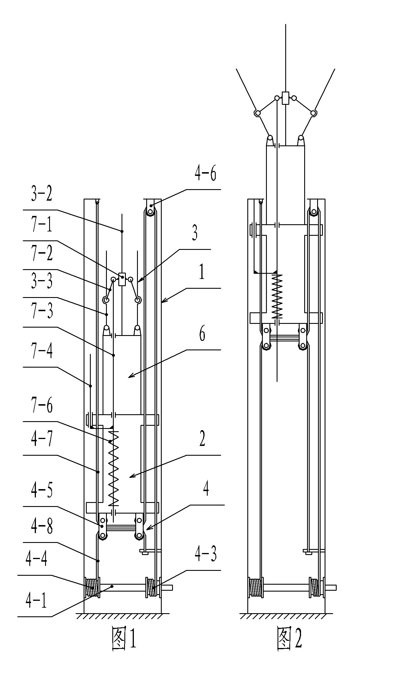
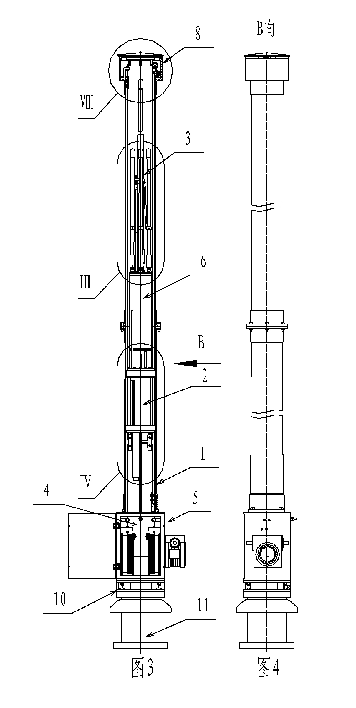
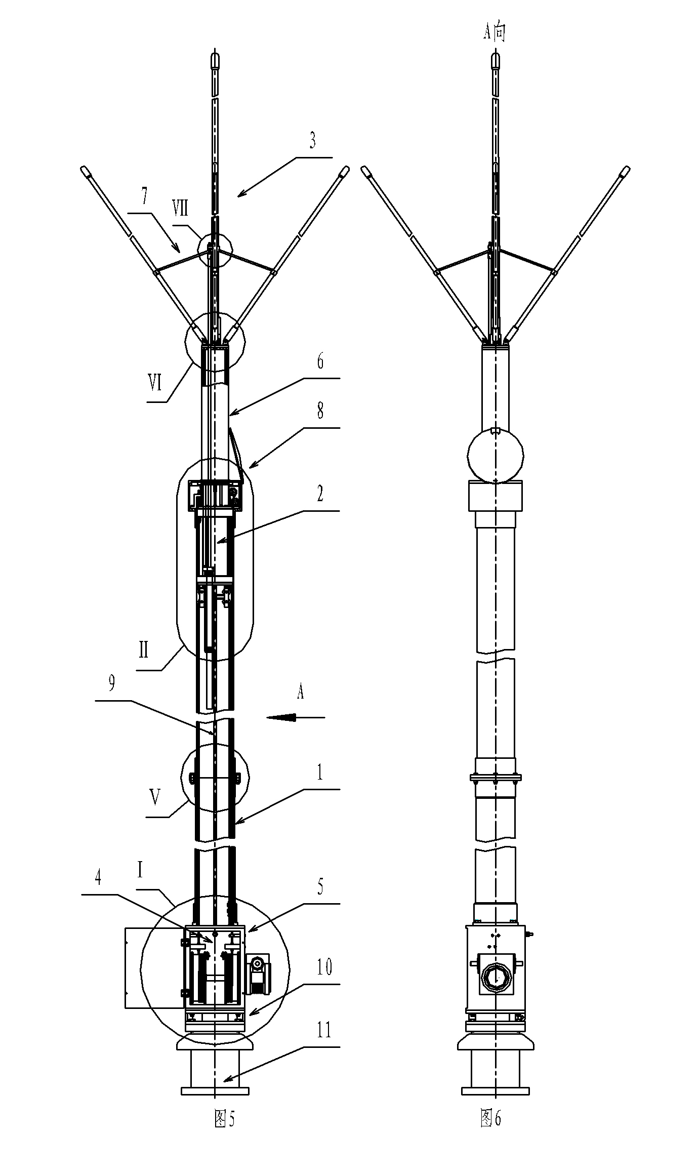
[0033] The specific embodiment of the present invention provides a telescopic antenna, which includes a hollow radiation rod 1, a guide tube 2 that is sleeved in the radiation rod 1 and can move up and down relative to the radiation rod 1, connected above the guide tube 2 and can follow the guide The cylinder 2 is synchronously lifted and lowered by the ejector rod assembly 3 and the lifting mechanism 4 connected between the radiation rod 1 and the guide cylinder 2 and used to drive the guide cylinder 2 to move up and down.

[0034] The bottom of the radiation rod 1 is fixedly connected with the cabinet 5, and the lifting mechanism 4 includes a transmission shaft 4-1 horizontally arranged in the cabinet 5, a driving device 4-2 for driving the rotation of the transmission shaft 4-1, and a transmission The lifting reel 4-3 coaxia...


PUM


Abstract

The invention relates to a telescopic antenna capable of stretching. The telescopic antenna is characterized by comprising a hollow radiation rod, a guide cylinder sleeved in the radiation rod and capable of lifting and moving relative to the radiation rod, a top rod assembly connected above the guide cylinder and capable of synchronously lifting along with the guide cylinder, and a lifting mechanism connected between the radiation rod and the guide cylinder and used for driving the guide cylinder to lift and move. The guide cylinder and the top rod assembly can be driven by the lifting mechanism to lift and move relative to the radiation rod; when the antenna does not need to work, the top rod assembly can be controlled to be totally contracted into the radiation rod so as to achieve theeffects of preventing the rain, dust, air and the sun, avoiding ageing, facilitating packing and transportation and the like; and when the antenna needs to work, the top rod assembly can be controlled to rise to a proper position, the effective height of the antenna is greatly increased so as to achieve better communication effect.

Description

technical field [0001] The invention relates to a telescopic antenna, in particular to a telescopic antenna for medium wave communication. Background technique [0002] The height of the existing medium-wave communication antenna is basically fixed. Since the antenna is not retractable as a whole, it is used on a mobile and small working platform such as a ship, which takes up space. The antenna has high wind resistance and weak wind resistance. Long-term exposure to the atmosphere is likely to cause aging and corrosion, which affects the life of the antenna, and it is inconvenient to pack and transport, and the effective height of the antenna is also greatly limited. Therefore, the application range of the existing medium-wave communication antenna is greatly limited. Contents of the invention [0003] In order to solve the above-mentioned problems in the prior art, the present invention provides a telescopic antenna that can make the antenna retractable. [0004] The te...

Claims


Application Information

Patent Timeline
IPC IPC(8): H01Q1/10
Inventor 陈吉锐吴保义毛起安郑振端林雅备李新辉
Owner FUJIAN XINGHAI COMM TECH
Why Eureka
Try Eureka