
Anti-pollution pin pulling device

A pin puller and anti-fouling technology, which is applied in the direction of suspension/strain insulators, pliers, overhead lines/cable equipment, etc., can solve the problems of difficulty in pulling out pins, small clamping force, and difficult to hold firmly and permanently, and achieve universal Wide range of performance, reliable performance, and complete functions

Inactive Publication Date: 2011-01-19
GUANGYUAN POWER SUPPLY COMPANY OF STATE GRID SICHUAN ELECTRIC POWER
View PDF5 Cites 8 Cited by
  • Summary
  • Abstract
  • Description
  • Claims
  • Application Information

AI Technical Summary

Problems solved by technology

[0002] When ordinary pin pulling pliers are performing live pin pulling operations, since the ball head of the anti-pollution insulator is deeply buried in the magnetic skirt of the insulator, the skirt of the insulator blocks the entry of the general pin pulling pliers. Homework, the operation of pulling out pins has brought great difficulty
At the same time, the holding force of the existing pin pulling pliers on the spring pins of insulators is completely dependent on the grip strength of the human hand, so there are disadvantages of small holding force and difficulty in holding firmly and lastingly

Method used


Image

  • Anti-pollution pin pulling device
  • Anti-pollution pin pulling device
  • Anti-pollution pin pulling device

Examples


Embodiment Construction

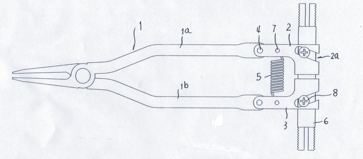
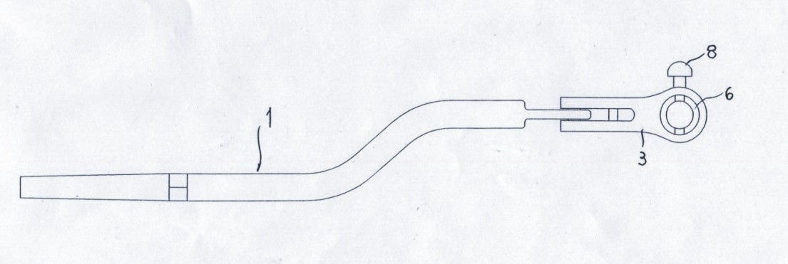
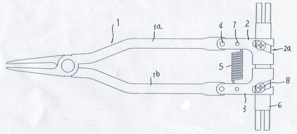
[0014] figure 1 , figure 2 It is shown that the pin puller 1 of the present invention has the same structure, left and right symmetrically arranged left support 3 and right support 2, wherein the right support 2 is formed by welding an lug plate on a pipe joint, and the pipe joint There is a strip-shaped notch 2a; the left and right handles of the pin pulling pliers 1 are curved in a "Z" shape, the left handle 1b of the pin pulling pliers is fixed to the ear plate of the left support, and the right handle of the pin pulling pliers 1a is fixed to the ear plate of the right support, and a tension spring 5 is fixedly connected between the ear plate of the left support and the ear plate of the right support. Among the two pipe joints of the seat, the two outer ends of the connecting pipe 6 protruding from the pipe joints are provided with threads and seams; the connecting pipe is left and right symmetrically screwed with two compression screws 8, and the two compression screws ...


PUM


Abstract

The invention relates to an anti-pollution pin pulling device belonging to a special instrument for pulling out a spring pin in power operation maintenance. The anti-pollution pin pulling device comprises a pair of pin pulling pliers and is also provided with a left supporting seat and a right supporting seat, wherein the right supporting seat is formed by welding a lug plate on a pipe joint; a left handle and a right handle of the pin pulling pliers are respectively in a 'Z' curved shape; the left handle of the pin pulling pliers is fixed with the lug plate of the left supporting seat; the right handle of the pin pulling pliers is fixed with the lug plate of the right supporting seat; a tension spring is fixedly connected between the lug plate of the left supporting seat and the lug plate of the right supporting seat; a connecting pipe for connecting an insulating tool is movably inserted into two pipe joints of the left supporting seat and the right supporting seat; threads and seams are arranged on two outer ends of the connecting pipe extending out of the pipe joints; two compression screws are symmetrically screwed on the connecting pipe from left to right; and the two compression screws are in compression joint on two strip-shaped notches on the two pipe joints of the left supporting seat and the right supporting seat. The invention has the characteristics of reliable performance, convenient use and wide universality and is suitable for hot-line installation and disassembly of spring pins of anti-pollution insulators and common insulators in power industry.

Description

technical field [0001] The invention relates to a pliers tool, in particular to a special tool for pulling out spring pins for live work in electrical maintenance. Background technique [0002] When ordinary pin pulling pliers are performing live pin pulling operations, since the ball head of the anti-pollution insulator is deeply buried in the magnetic skirt of the insulator, the skirt of the insulator blocks the entry of the general pin pulling pliers. Homework, the operation of pulling out pins has brought great difficulty. Simultaneously, the clamping force of the existing pin pulling pliers to the spring pin of the insulator depends entirely on the grip strength of the human hand, so there are disadvantages that the clamping force is small and the clamping is difficult to be stable and durable. Contents of the invention [0003] The object of the present invention is to provide an anti-pollution pin puller with stable clamping, reliable performance and convenient use...

Claims


Application Information

Patent Timeline
IPC IPC(8): H02G1/02H01B17/04B25B7/22B25B27/14
Inventor 田刚
Owner GUANGYUAN POWER SUPPLY COMPANY OF STATE GRID SICHUAN ELECTRIC POWER
Learn More