
Modularized combined motor stator structure and application thereof

A motor stator and combined technology, applied in the direction of magnetic circuit shape/style/structure, magnetic circuit static parts, etc., can solve problems such as limited radial strength, high processing accuracy requirements, structural deformation, etc., to reduce manufacturing costs , Improve fault tolerance, improve the effect of slot full rate

Inactive Publication Date: 2011-01-19
ZHEJIANG UNIV
View PDF8 Cites 11 Cited by
  • Summary
  • Abstract
  • Description
  • Claims
  • Application Information

AI Technical Summary

Problems solved by technology

Although this can improve the slot fill rate of the motor, the adjacent stator tooth modules are connected by meshing, because the stator tooth modules are all made of silicon steel sheets, and the processing accuracy of the silicon steel sheets is high, which usually requires advanced processing such as high-speed punching machines. equipment, otherwise it is difficult to meet the accuracy requirements of assembly
The patent (patent number: ZL200620020255.5) disassembles the stator into several single teeth, and the meshing connection is also used between adjacent stator teeth, and the positioning is guaranteed by welding, screw fastening and meshing connection between adjacent stator tooth modules And strength, also have high requirements for machining accuracy, and the radial strength is limited, especially when the radial force is large, the structure may appear structural deformation

Method used


Image

  • Modularized combined motor stator structure and application thereof
  • Modularized combined motor stator structure and application thereof
  • Modularized combined motor stator structure and application thereof

Examples


Embodiment Construction

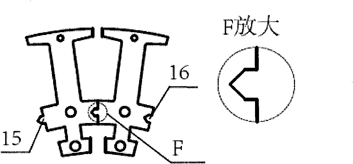
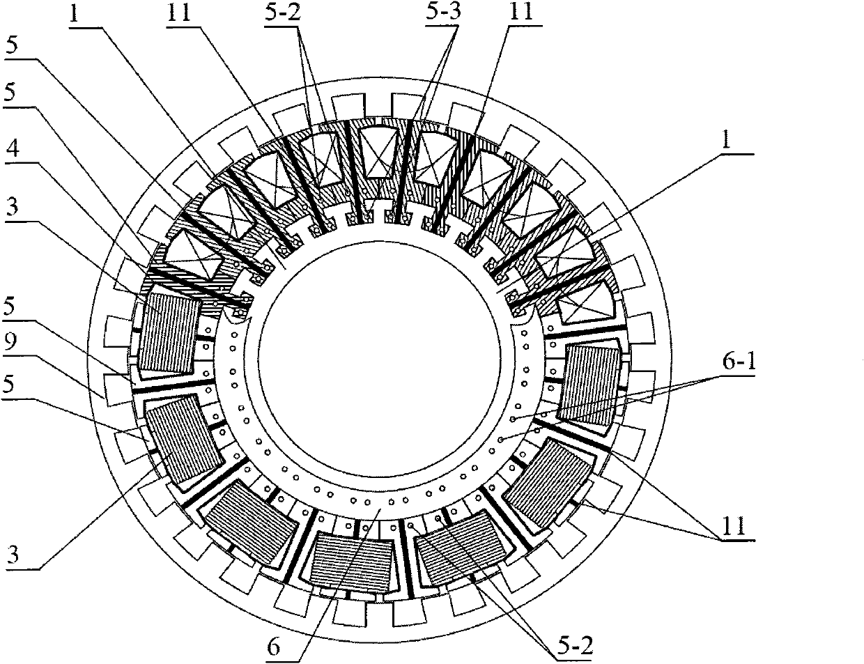
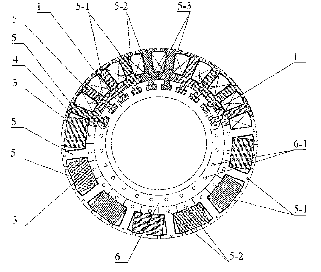
[0025] figure 1 Shown is the modular combined stator structure of the present invention for the outer rotor / inner stator motor, the structure includes: a cylindrical stator support 1 and a stator tooth core 5, the outer surface of the cylindrical stator support 1 is evenly distributed with bottom width , The narrow "T" groove at the opening, the stator tooth core such as figure 2 As shown, it includes crown a, tooth body b, tooth yoke c and tooth root d. The stator tooth core 5 is formed by lamination and fastening of stator tooth punching sheets. In the illustrated example, there is a through hole 5- 1. There is a through hole 5-2 on the yoke c, and the stator tooth core 5 is fastened by fasteners passing through the through hole 5-1 on the tooth crown a of the stator tooth punch and the through hole 5-2 on the tooth yoke c ; Or the stator tooth core 5 can also be fastened by the crown and the rivet buckle on the tooth yoke. The dedendum d of each stator tooth core 5 is pl...


PUM


Abstract

The invention discloses a modularized combined motor stator structure which comprises a cylindrical or annular stator bracket and stator tooth iron cores, wherein T-shaped grooves the bottom parts of which are wide and the opening parts of which are narrow are uniformly distributed on the outer surface of the cylindrical stator bracket or the inner surface of the annular stator bracket; each stator tooth iron core is formed by laminating and fastening stator tooth punching sheets; each stator tooth iron core comprises a tooth crown, a tooth body, a tooth yoke and a tooth root; the tooth root of each stator tooth iron core is respectively arranged in each groove of the stator bracket; the shape of each tooth root is matched with the shape of each T-shaped groove of the stator bracket; all the stator tooth iron cores are fixed with the stator bracket into a whole by utilizing fasteners which pass through the upper through holes of tooth roots and the upper through holes of annular press plates positioned at the two ends of the stator bracket; the stator tooth iron cores installed on the stator bracket are sequentially wound with coils alternately; an insulated winding frame is arranged between each coil and each stator tooth iron core; and the coils on all the stator tooth iron cores are connected in series or in parallel to form a stator winding of a motor. The invention can effectively improve the space factor of the motor and reduce the manufacturing cost.

Description

technical field [0001] The invention relates to a modularized combined motor stator structure, which belongs to the technical field of motors. Background technique [0002] For traditional motors, due to the limitation of the slot opening, especially the inner rotor / outer stator motor, it is difficult to directly wind or insert the winding, and the slot fill rate is low, and the manufacturing cost is high. The existing direct winding technology patent (US Patent No.: US20090302694) proposes a method of dismantling the outer stator of the motor into several teeth, and inserting the pre-wound winding and insulating layer into the stator teeth together, and then the stator The teeth are assembled into a whole; although this can achieve the purpose of improving the motor slot full rate, this structure is only suitable for the inner rotor / outer stator structure; in the outer rotor / inner stator structure, the stator structure obtained by such assembly will be due to the motor radi...

Claims


Application Information

Patent Timeline
IPC IPC(8): H02K1/14H02K1/17
Inventor 沈建新王灿飞
Owner ZHEJIANG UNIV
Learn More