Radial magnetic field modulating brushless double-rotor motor

A dual-rotor motor and radial magnetic field technology, applied in the direction of magnetic circuit rotating parts, electrical components, electromechanical devices, etc., can solve the problems of reduced operating efficiency and reliability, and achieve cost reduction, volume reduction, and overcome operational problems. The effect of reduced efficiency

Active Publication Date: 2011-01-19
HARBIN INST OF TECH
View PDF2 Cites 41 Cited by
  • Summary
  • Abstract
  • Description
  • Claims
  • Application Information

AI Technical Summary

Problems solved by technology

[0004] The purpose of the present invention is to solve the problem that the rotating winding in the existing dual-rotor motor needs to introduce current through brushes and slip rings, resulting in a decrease in operating efficiency and reliability, as well as the frequent maintenance of components such as brushes, and provides a A Radial Magnetic Field Modulation Type Brushless Dual Rotor Motor

Method used


Image

  • Radial magnetic field modulating brushless double-rotor motor
  • Radial magnetic field modulating brushless double-rotor motor
  • Radial magnetic field modulating brushless double-rotor motor

Examples


specific Embodiment approach 1

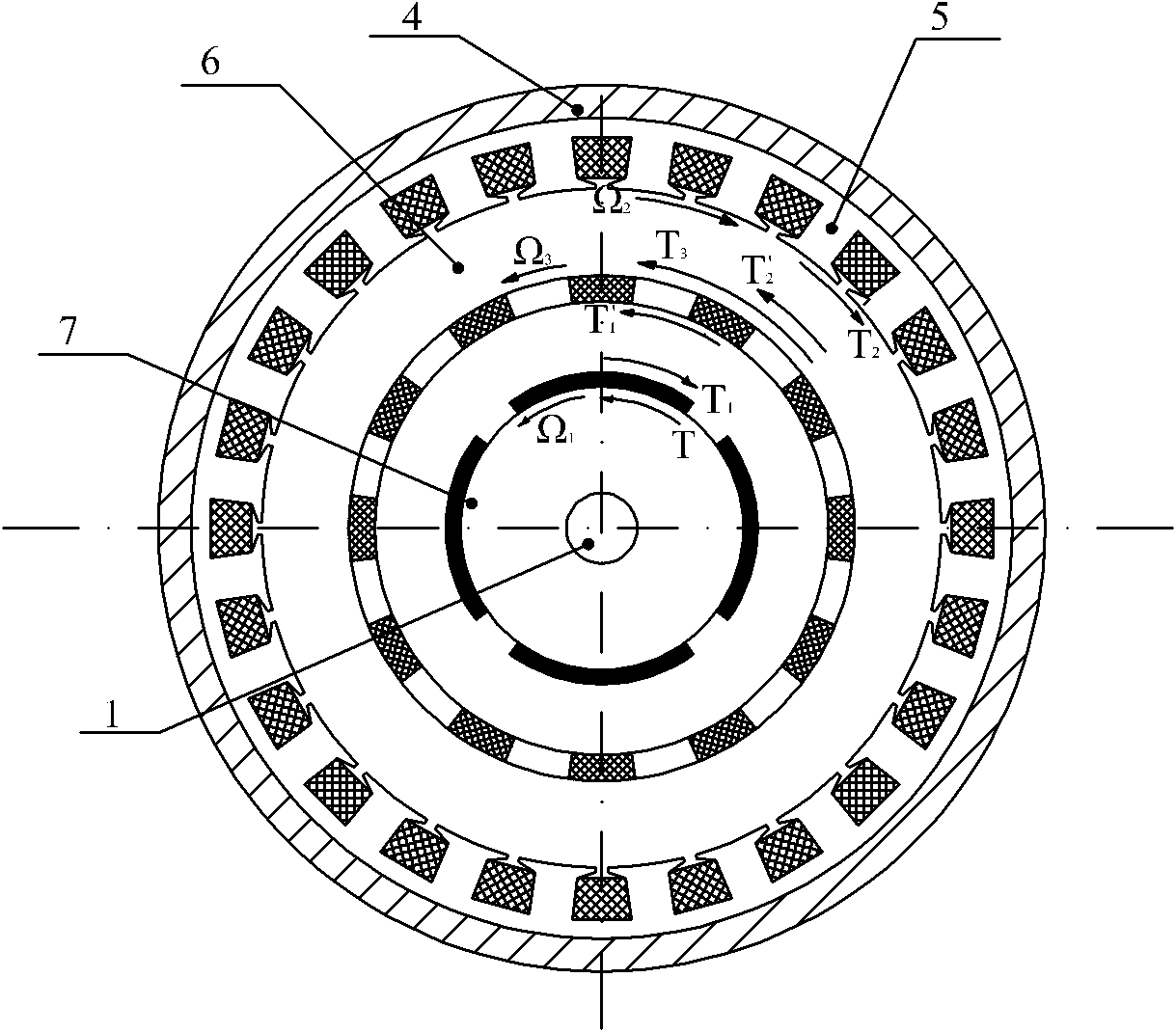
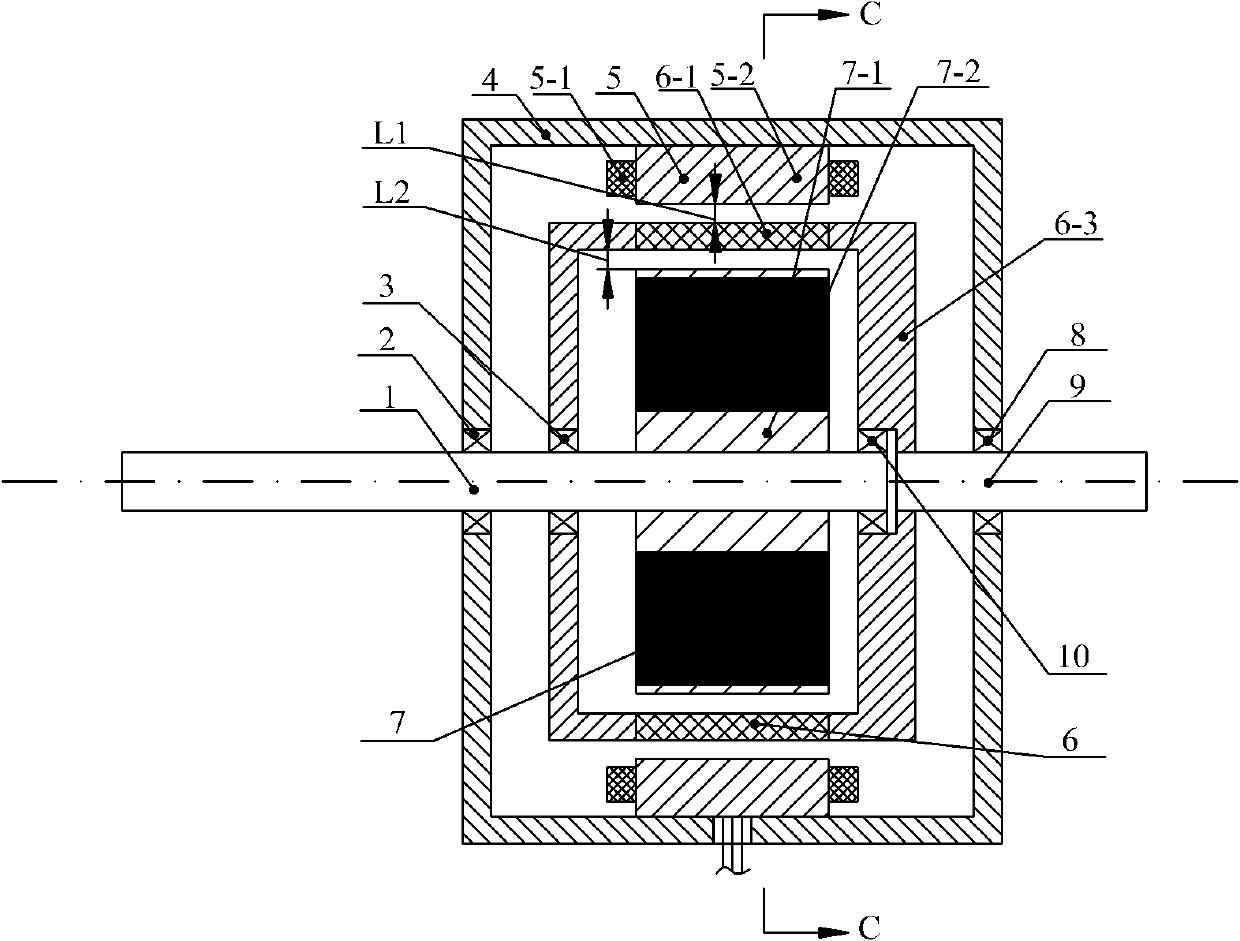
[0024] Specific implementation mode one: the following combination Figure 1 to Figure 11 Describe this embodiment, this embodiment includes housing 4, stator 5, permanent magnet rotor 7, permanent magnet rotor output shaft 1, modulation ring rotor 6 and modulation ring rotor output shaft,

[0025] The stator 5 is fixed on the inner wall of the housing 4, the permanent magnet rotor 7 is fixed on the output shaft 1 of the permanent magnet rotor, the modulation ring rotor 6 is located between the stator 5 and the permanent magnet rotor 7, and the output shaft 1 of the permanent magnet rotor passes through the first The bearing 2 is rotatably connected to the housing 4, and the permanent magnet rotor output shaft 1 is rotatably connected to the modulating ring rotor 6 through the second bearing 3 and the fourth bearing 10, and one end of the modulating ring rotor output shaft is fixed on the modulating ring rotor 6, and The output shaft of the modulation ring rotor is rotationall...

specific Embodiment approach 2

[0054] Specific implementation mode two: the following combination figure 1 with figure 2 Describe this embodiment, the difference between this embodiment and Embodiment 1 is that the permanent magnet unit 7-1 is arranged on the outer circular surface of the permanent magnet rotor core 7-2, and the permanent magnet unit 7-1 is magnetized along the radial direction Or magnetize in parallel in the radial direction, and other structures and connection methods are the same as those in Embodiment 1.

specific Embodiment approach 3

[0055] Specific implementation mode three: the following combination image 3 with Figure 4 This embodiment is described. The difference between this embodiment and Embodiment 1 is that the permanent magnet unit 7-1 is embedded in the outer circular surface of the permanent magnet rotor core 7-2, and the permanent magnet unit 7-1 is filled radially. Magnetization or parallel magnetization along the radial direction, other structures and connection methods are the same as those in Embodiment 1.


PUM


Abstract

The invention provides a radial magnetic field modulating brushless double-rotor motor, belonging to the field of motors. The invention aims to solve the following problem: rotating windings in the existing double-rotor motors need electric brushes and slip rings to introduce current, so that the operation efficiency and the reliability are reduced and the parts such as the electric brushes need to be frequently maintained. The motor is characterized in that stators of the motor are fixed on the inner side walls of a shell; a permanent magnet rotor is fixed on a permanent magnet rotor output shaft; a modulation ring rotor is arranged between the stators and the permanent magnet rotor; the permanent magnet rotor output shaft is connected with the shell and the modulation ring rotor in a rotary manner; one end of the permanent magnet rotor output shaft is fixed on the modulation ring rotor and is connected with the shell in a rotary manner; the stators are electrified to form 2p-numbered pole magnetic fields; 2n-numbered permanent magnet units of the permanent magnet rotor are uniformly distributed and arranged on the excircle surface of a permanent magnet rotor core along the circumferential direction; the permanent magnet rotor rotates to form 2n-numbered pole magnetic fields; q-numbered magnetic blocks and q-numbered insulating blocks interlace on the excircle surface of a support of the modulation ring rotor along the circumference direction; and p is equal to hn plus kq.

Description

technical field [0001] The invention relates to a radial magnetic field modulation type brushless double-rotor motor, which belongs to the field of motors. Background technique [0002] The dual-rotor motor has two rotors and rotating shafts with independent rotational speeds, which can realize dual-axis independent drive, so it has broad application prospects in electric vehicles, wind power generation, torpedo propulsion and other occasions. [0003] A common method for realizing dual-shaft drive in existing dual-rotor motors is to use the rotor of the traditional motor as one rotor and connect it to a rotating shaft, and rotate the stator of the traditional motor as another rotor and connect it to another rotating shaft. Among them, one rotating shaft is connected to the prime mover as the energy input end, and the other rotating shaft is connected to the load as the energy output end. By adjusting the frequency of the current in the rotating stator winding, the input sha...

Claims


Application Information

Patent Timeline
Patent Type & Authority Applications(China)
IPC IPC(8): H02K16/02H02K1/27H02K1/22H02K1/16
Inventor 郑萍白金刚佟诚德隋义吴芊柯文静
Owner HARBIN INST OF TECH
Why Eureka
Try Eureka