Method used for balancing three phases of direct current side voltages of chain power regulating device

A DC side voltage and power adjustment technology, applied in the output power conversion device, the conversion of AC power input to DC power output, electrical components, etc. Limits and other issues, to achieve the effect of being beneficial to engineering practice, less control parameters, and less calculation.

Active Publication Date: 2011-01-19
TSINGHUA UNIV
View PDF1 Cites 25 Cited by
  • Summary
  • Abstract
  • Description
  • Claims
  • Application Information

AI Technical Summary

Problems solved by technology

The hardware control method increases the complexity and cost of the device, and the current two software control methods, for the zero-sequence voltage injection to realize the three-phase DC side voltage balance control, the zero-sequence voltage injection does not change the phase current of each phase, only changes For each phase voltage, when the voltage imbalance of the three-phase DC side is large, it is very limited to use the unbalanced power generated by zero-sequence voltage injection to compensate the active power imbalance between the three phases, because the DC bus voltage of the actual system is limited, which makes the amplitude of the output zero-sequence voltage also limited
Secondly, for large-capacity inverters, due to the small adjustment range of the phase angle, it is difficult to implement the DC voltage balance control method of controlling the phase angle of the output voltage of each unit inverter with DC side voltage feedback.

Method used


Image

  • Method used for balancing three phases of direct current side voltages of chain power regulating device
  • Method used for balancing three phases of direct current side voltages of chain power regulating device
  • Method used for balancing three phases of direct current side voltages of chain power regulating device

Examples


Embodiment Construction

[0026] The invention proposes a method for balancing the three-phase DC side voltage of a chain-type power regulating device. The detailed process of solving the negative sequence voltage is as follows: figure 1 shown, including the following steps:

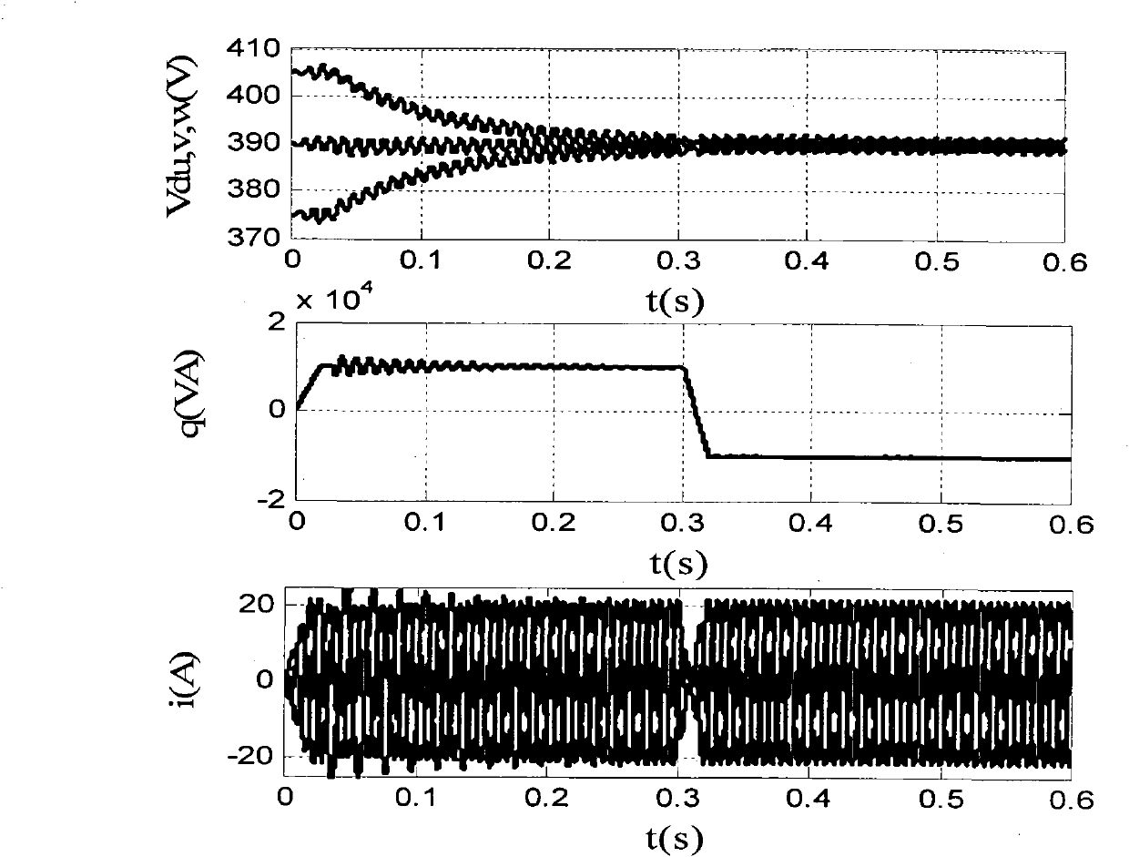
[0027] (1) Obtain the DC side voltage of each H-bridge unit of the chain-type power regulator through the voltage sensor, denoted as: V du1 ..V dwn , V dv1 ..V dvn , V dw1 ..V dwn , where n represents the cascade number of each phase;

[0028] (2) According to the above DC side voltage, use the filter formula to filter out the 2ω ripple in the DC side voltage, and obtain the DC side voltage after filtering the ripple Among them, ω is the electrical angle of the power supply voltage;

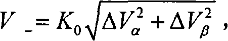
[0029] (3) Using the formula Find the three-phase DC side voltage

[0030] (4) According to the DC side voltage of the above three phases use the formula Get the average value V of the three-phase DC side voltage d ;

[0031] (5)...


PUM


Abstract

The invention relates to a method used for balancing three phases of direct current side voltages of a chain power regulating device, and belongs to the technical field of the control of power electronic devices. The method comprises the following steps of: acquiring direct current side voltages of each H-bridge unit in the three phases of a chain power regulating system; filtering ripples from the direct current side voltages; taking the direct current side voltages of which the ripples are filtered as feedback signals; calculating an average value of the three phases of the direct current side voltages based on the direct current side voltages; taking difference values between the three phases of the direct current side voltages and the average value as command signals; calculating an amplitude value and a phase angle of a negative sequence voltage according to the difference values by utilizing corresponding formulae; obtaining a required negative sequence according to an electric angle of a power supply voltage at a device grid place; and after the negative sequence voltage is superposed to an output voltage command used for power control in the device, driving the device to output an alternating current voltage so as to realize the balance control of the three phases of the direct current side voltages. The method of the invention has the characteristics of software implementation, simple algorithm, obvious effect and contribution to engineering application.

Description

technical field [0001] The present invention relates to a method for balancing the three-phase DC side voltage of a chained (also called: cascaded) power regulating device, in particular to a chained power with multiple independent DC buses based on negative-sequence voltage injection balance The invention relates to a method for controlling the three-phase DC side voltage of an electronic power conversion device, which belongs to the technical field of power electronic device control. Background technique [0002] Chain-link converters have been widely used in high-power, medium- and high-voltage drive systems due to their simple structure and modularization. In recent years, with the increasing grid-connected capacity of renewable energy power generation systems such as wind power generation, it is necessary to install power electronic devices capable of adjusting active and reactive power at the grid-connected places of these systems to solve the power generated by their ...

Claims


Application Information

Patent Timeline
Patent Type & Authority Applications(China)
IPC IPC(8): H02M7/217
Inventor 杨耕万承宽耿华
Owner TSINGHUA UNIV
Why Eureka
Try Eureka