E1 link-based bidirectional time-frequency synchronous transmission method and master-slave device

A main device, time-frequency technology, applied in the field of communication, can solve the problems of PTP data packet timing accuracy decline, affecting system performance and synchronization accuracy, Ethernet data packet delay uncertainty, etc. Protocol conversion, effect without caching

Active Publication Date: 2011-01-19
电信科学技术第五研究所有限公司 +1
View PDF2 Cites 38 Cited by
  • Summary
  • Abstract
  • Description
  • Claims
  • Application Information

AI Technical Summary

Problems solved by technology

Due to the rate mismatch, the ETHERNET / E1 protocol converter has a buffer mechanism, so the delay of the Ethernet data packet passing through the protocol converter is uncertain
This uncertain transmission delay has little impact on general Ethernet data services, but it will cause a decrease in timing accuracy for PTP data packets
The delay jitter of the traditional ETHERNET / E1 protocol converter can reach tens of microseconds, even if the method of forwarding PTP data packets is adopted, the delay jitter will still be several microseconds
Moreover, directly encapsulating the Ethernet PTP data packet into the E1 data, because it contains the Ethernet parameter bytes, the overhead is relatively large, and the excessive length of the encapsulated data will affect the system performance and synchronization accuracy

Method used


Image

  • E1 link-based bidirectional time-frequency synchronous transmission method and master-slave device
  • E1 link-based bidirectional time-frequency synchronous transmission method and master-slave device
  • E1 link-based bidirectional time-frequency synchronous transmission method and master-slave device

Examples


Embodiment Construction

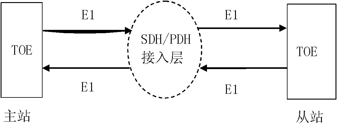
[0043] see Figure 1~3 .

[0044] The two-way time-frequency simultaneous interpretation process of the present invention is:

[0045] A. The master station sends a time synchronization frame to the slave station, and the master station records the time stamp T1 of the synchronization frame sending packet and inserts it into the synchronization frame;

[0046] B. The slave station receives the synchronization frame sent by the master station, records the packet receiving time stamp T2, and obtains the time stamp T1 from the synchronization frame;

[0047] C. The slave station sends a delay request frame to the master station, and records the time stamp T3 of sending the delay request frame;

[0048] D. The master station receives the delay request frame sent by the slave station and records the received packet timestamp T4, and the master station inserts the T4 timestamp into the delay feedback frame and sends it to the slave station;

[0049] E. The slave station receives ...


PUM


Abstract

The invention discloses an E1 link-based bidirectional time-frequency synchronous transmission method and a master-slave device, and relates to communication technology. The method comprises the following steps that: A, a master station transmits a time synchronous frame to a slave station, records a synchronous frame packet transmitting time stamp T1 and inserts the time stamp T1 into the synchronous frame; B, the slave station receives the synchronous frame from the master station, records a packet receiving time stamp T2 and acquires the time stamp T1 from the synchronous frame; C, the slave station transmits a time delay request frame to the master station and records the time stamp T3 for transmitting the time delay request frame; D, the master station receives the time delay request frame transmitted by the slave station and records the packet receiving time stamp T4, and the master station transmits the time stamp T4 to the slave station; and E, the slave station acquires the time stamp T4, calculates line loop time delay D, master-slave time deviation and frequency deviation according to the acquired time stamps T1 to T4 so as to adjust local time and clock frequency, wherein information in each step is encapsulated to be in an E1 frame format. The method and the device have the advantages of no need of protocol conversion or cache and low expenditure, so data transmitting and receiving time delay jitter can be greatly reduced.

Description

technical field [0001] The present invention relates to communication technology. Background technique [0002] PTP (IEEEE 1588) is a precision time synchronization protocol standard that can provide time synchronization functions based on network connections between master and slave devices. The PTP protocol adopts a combination of software and hardware, and the physical layer is stamped by the hardware, and the synchronization accuracy between the master and the slave can reach the microsecond level. PTP synchronization accuracy will be affected by factors such as network traffic changes and delay jitter. Therefore, synchronization accuracy cannot be guaranteed when performing multi-hop, long-distance transmission. At present, the PTP protocol cannot perform high-precision remote transmission on traditional routers or switches. [0003] The current transmission network takes the SDH transmission network as the main body. SDH technology occupies a dominant position in th...

Claims


Application Information

Patent Timeline
Patent Type & Authority Applications(China)
IPC IPC(8): H04L7/00H04B7/26H04L29/06
CPCH04J3/065
Inventor 王广才傅俊鹏
Owner 电信科学技术第五研究所有限公司
Why Eureka
Try Eureka