High-pressure and impact resistant bearing roller bit with elastic sliders

A roller cone bit, impact-resistant technology, applied in drill bits, drilling equipment, earth-moving drilling, etc., can solve problems such as the impact of broken teeth of the roller cone, damage to the inner hole of the cone, and damage to the sealing system, so as to achieve smooth operation of the drill bit and avoid Severe vibration, good protective effect

Active Publication Date: 2011-01-26
TIANJIN LILIN BIT
View PDF4 Cites 3 Cited by
  • Summary
  • Abstract
  • Description
  • Claims
  • Application Information

AI Technical Summary

Problems solved by technology

Since the palm journal and the inner hole of the cone are both rigid, the deformation will not be large, so the contact area between the palm journal and the inner hole of the cone is restricted, so that the contact area, that is, the force-bearing area, is in the cross-sectional direction It can be seen that most of them are kept within the range of 60 degrees, and as the distance from the bottom becomes farther away, the force received also drops sharply, while the force at the bottom is very large, resulting in the gap between the journal of the tooth palm and the inner hole of the cone. The force is highly concentrated in a small range at the bottom, and the resulting disadvantages are: 1. The total load that the roller cone bit can bear is not large; 2. If the force is too concentrated, it is easy to cause damage to the inner hole of the roller cone; 3. The sealing system is unfavorable. Most of the gaps between the palm journal and the inner hole of the cone, the lack of constraints on the cone, will produce severe vibration, and the cone can vibrate about 600 times per minute, causing great damage to the sealing system; 4 , has a certain influence on the broken teeth of the gear

Method used


Image

  • High-pressure and impact resistant bearing roller bit with elastic sliders
  • High-pressure and impact resistant bearing roller bit with elastic sliders
  • High-pressure and impact resistant bearing roller bit with elastic sliders

Examples


Embodiment Construction

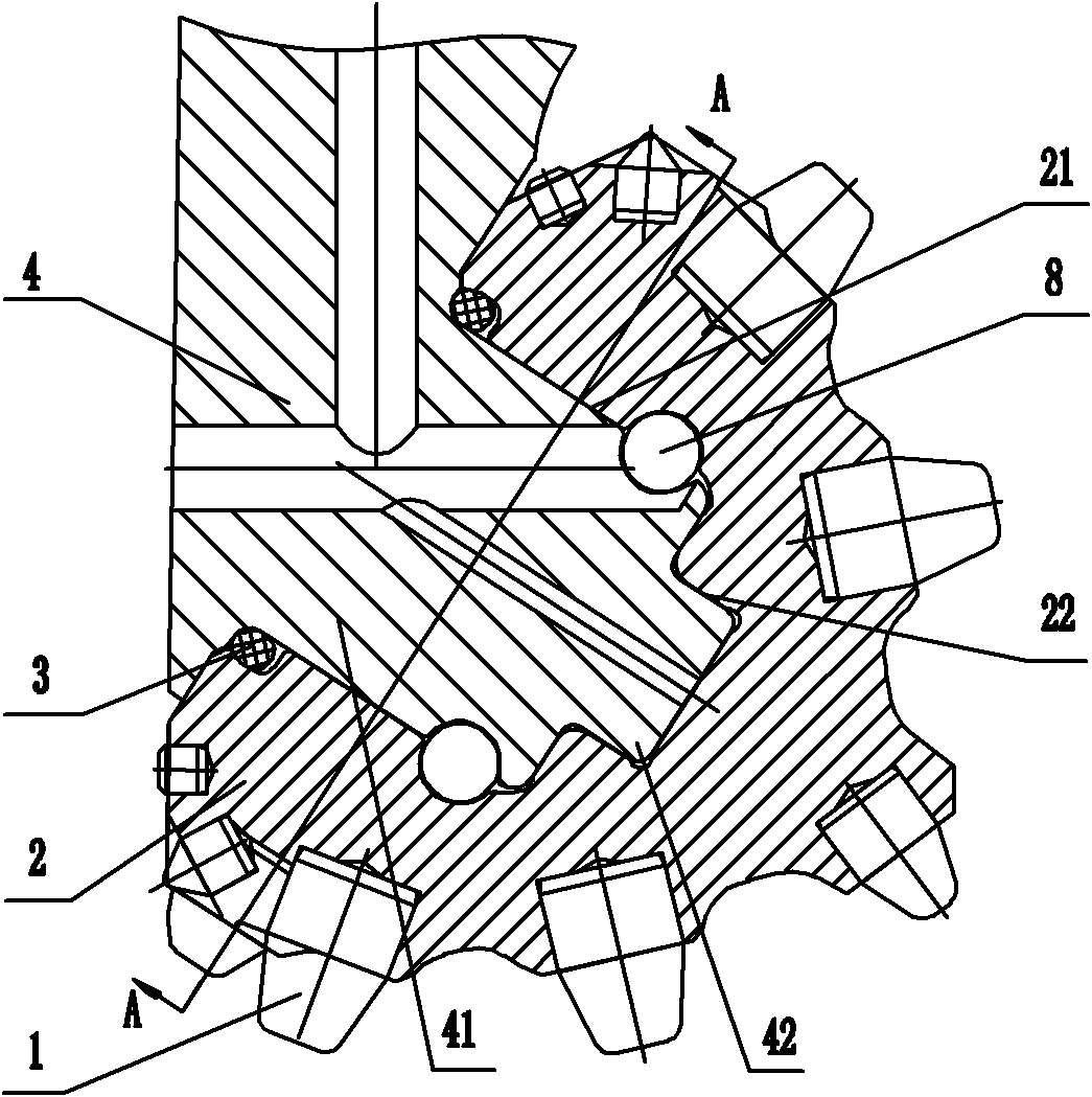
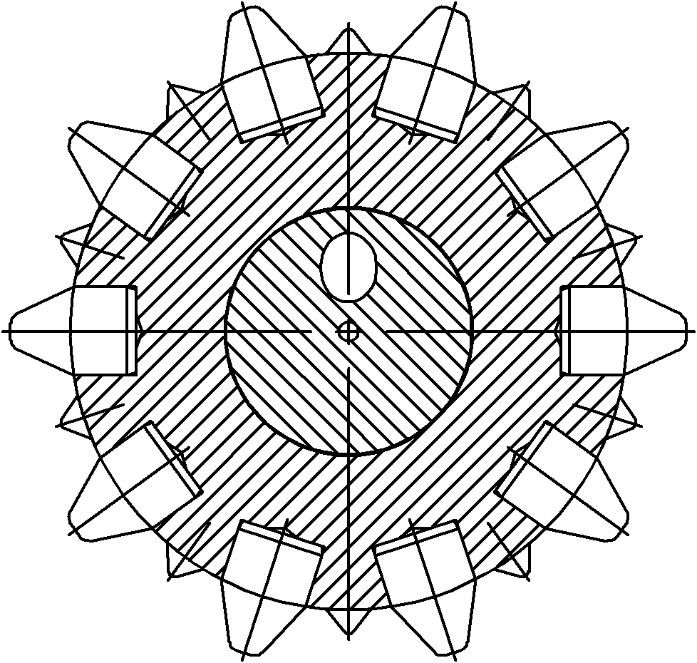
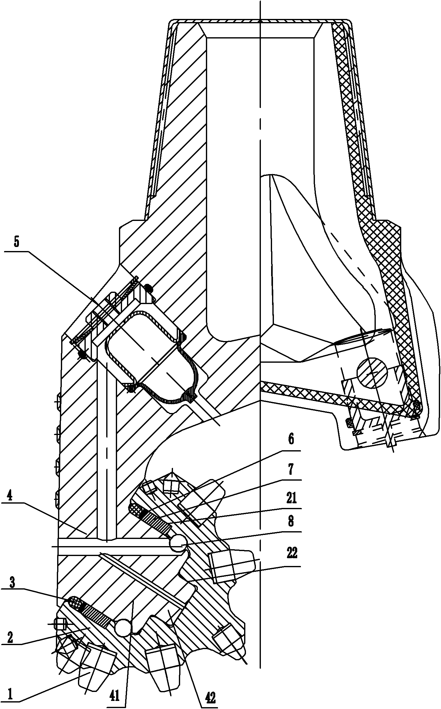
[0023] Referring to the accompanying drawings, a high-pressure and impact-resistant roller cone bit of the present invention includes a cone 2 inlaid with alloy teeth 1, a tooth palm 4 with a large journal 41 and a small journal 42, and the cone 2 is provided with a large journal correspondingly. The shaft hole 21 and the small shaft hole 22, the large shaft hole 21 and the small shaft hole 22 of the cone are respectively set on the large shaft journal 41 and the small shaft journal 42 of the tooth palm journal, and the tooth palm 4 is also equipped with an oil supply system 5. Rubber sealing ring 3, gasket 6 and locking ball 8.

[0024] On the inner wall of the large shaft hole 21, there are annular slides distributed around the axis of the large shaft hole 21. A plurality of elastic sliders 7 are installed in the annular slides. Cooperate.

[0025] The elastic slider 7 is an arc shoe type, and all the elastic sliders are put together in the annular slideway in sequence, for...


PUM


Abstract

The invention discloses a high-pressure and impact resistant bearing roller bit with elastic sliders, comprising a roller and a palm, wherein the palm is provided with a big journal and a small journal; and the roller is provided with a big axle hole and a small axle hole. The roller bit is characterized in that a slide way is arranged on the inner wall of the big axle hole; the big axle hole and the small axle hole of the roller are respectively sleeved on the big journal and the small journal of the palm; the slide way is provided with at least two elastic sliders; and the inner wall of the big axle hole is fit with the outer wall of the big journal of the palm in a sliding friction manner via the elastic sliders. The sliders have prestressing force between the axle holes and the journals to ensure that most surfaces between the journals of the palm and the axle holes of the rollers are pressed, thus reducing the intensity of pressure between the axle holes and the journals to ensure the bearing to bear greater load. The gaps between the axle holes and the journals disappear, thus reducing relative vibration between the roller and the palm and having good protective effects on sealing of the roller bit and alloy gears.

Description

technical field [0001] The invention relates to a roller cone bit used for oil field drilling and geological exploration, in particular to a high pressure and impact resistant roller cone bit. Background technique [0002] At present, roller cone bits are widely used in the fields of oilfield drilling and geological exploration. As shown in Figure 1, the roller cone bit is mainly composed of a roller cone 2 and a tooth palm 4. The roller cone 2 is connected to the tooth palm through a sliding bearing or a rolling bearing structure. The tooth palm 4 is provided with a large journal 41 and a small journal 42, and the cone 2 is correspondingly provided with a large shaft hole 21 and a small shaft hole 22, and the large shaft hole 21 and the small shaft hole 22 of the cone are respectively sleeved on the large On the journal 41 and the small journal 42, the cone 2 is locked on the large journal 41, that is, on the tooth palm 4, by a circle of ring shaft locking balls 8 arranged ...

Claims


Application Information

Patent Timeline
Patent Type & Authority Applications(China)
IPC IPC(8): E21B10/22E21B10/24E21B10/25
Inventor 薛中学
Owner TIANJIN LILIN BIT
Why Eureka
Try Eureka