
Manufacturing WTG blade having a spar

A technology of wind turbines and wind turbines, applied in wind engines, wind engines consistent with the wind direction, wind power generation, etc., can solve problems such as increasing WTG costs, and achieve the effect of improving consistency

Active Publication Date: 2015-02-11
VESTAS WIND SYST AS
View PDF5 Cites 0 Cited by
  • Summary
  • Abstract
  • Description
  • Claims
  • Application Information

AI Technical Summary

Problems solved by technology

[0008] yet another possible drawback of one or more of the existing solutions is that the mechanisms and systems used to prevent vibration or unforeseen aerodynamic lift may themselves add to the cost of the WTG

Method used


Image

  • Manufacturing WTG blade having a spar
  • Manufacturing WTG blade having a spar
  • Manufacturing WTG blade having a spar

Examples


Embodiment Construction

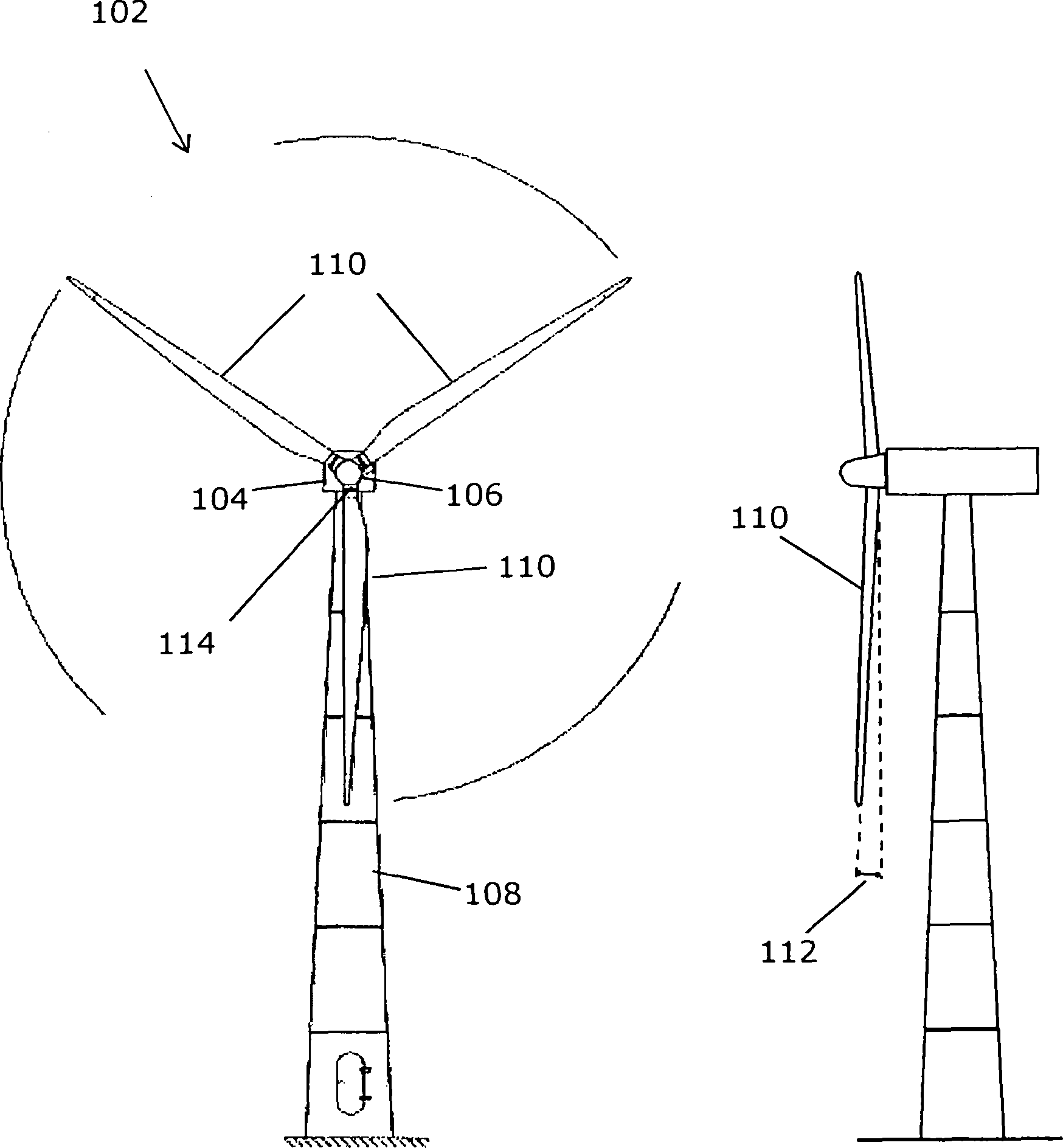
[0063] figure 1 A wind turbine generator 102 is shown having a nacelle 104 and a hub 106 pivotally mounted on the nacelle 104 by a shaft. The nacelle 104 is mounted on a wind turbine tower 108 via a swivel joint. The hub 106 of the wind turbine includes three wind turbine blades 110 connected to the hub at blade root ends 114 . The hub rotates about the central axis of the rotor shaft of the wind turbine in a rotational plane substantially perpendicular to the central axis. In the example shown the length of the wind turbine blade is about 40 meters, but the blade length can also generally be between 25 and 75 meters.

[0064] In the plane of rotation of the blades, it can be seen from the figure that the blades are separated from each other by a sweep angle of 120 degrees. A side view of the wind turbine is shown on the right side of the figure. As can be seen from the side view, the wind turbine blade is tapered with a cone angle 112 offset from the plane of rotation. ...


PUM

PropertyMeasurementUnit
lengthaaaaaaaaaa
lengthaaaaaaaaaa

Abstract

In order within the field of wind turbines generators (WTG) 102 e.g. to provide a consistent way of manufacturing a WT blade 110 there is disclosed a blade mould 402 and a blade spar fixture 408 to support the spar 202 in the mould so as to provide a fixed predetermined relative position, and preferably also orientation, between at least a root end, such as a bushing 204 in the root end of the blade spar 202, and a root end of the mould. Overall consistency is also obtained in that hereby a blade with anticipated aerodynamic and strength characteristics is provided, among others in that at least adjacent to the root of the spar there is substantially the same distance for a cured adhesive between an innermost surface 1504 of each of blade shells 304, 306 and an outermost surface 1502 of the spar.

Description

technical field [0001] The invention relates to a wind turbine generator blade and a mold for a wind turbine generator blade, and to a method of manufacturing a wind turbine generator blade with a spar. Background technique [0002] The blade of a wind turbine generator (WTG or just WT) is an elongated structure with an airfoil profile adapted to provide aerodynamic lift by relative motion through the air. Herein, the blades of the WTG are interchangeably referred to as "rotor blades" or "wind turbine blades" or "blades". [0003] Factors such as the aerodynamic lift generated by the blade, any noise generated as the blade passes through the air, and the wear resistance of the blade can vary depending on the shape of the blade, the size of the blade, the configuration of the blade, the angle of attack, the materials used to make the blade , or changes in the way the blades are manufactured. A blade that does not produce the desired aerodynamic lift may cause unforeseen loa...

Claims


Application Information

Patent Timeline
Patent Type & Authority Patents(China)
IPC IPC(8): F03D1/06B29C65/48B29C33/00B29L31/08
CPCF03D1/0675B29L2031/085F05C2253/04B29L2031/082Y10T29/53983F05B2280/6003Y10T29/53974Y10T29/49336Y10T29/49316B29D99/0025Y02E10/721Y10T29/49899Y02E10/72Y02P70/50
Inventor L·K·彼得森O·戴维斯
Owner VESTAS WIND SYST AS
Learn More