Heat exchanger for improving drainage performance

A drainage performance and heat exchanger technology, applied in heat exchange equipment, evaporator/condenser, lighting and heating equipment, etc., can solve the problems of deteriorating defrosting, difficult defrosting, thick frosting, etc., and achieve improved drainage performance , Improve the effect of heat transfer performance

Inactive Publication Date: 2011-01-26
GD MIDEA AIR-CONDITIONING EQUIP CO LTD
View PDF6 Cites 8 Cited by
  • Summary
  • Abstract
  • Description
  • Claims
  • Application Information

AI Technical Summary

Problems solved by technology

Especially for the working conditions where frosting may occur, the lower part of the heat exchanger is easy to freeze, and all the condensed water and

Method used


Image

  • Heat exchanger for improving drainage performance
  • Heat exchanger for improving drainage performance
  • Heat exchanger for improving drainage performance

Examples


Embodiment 1

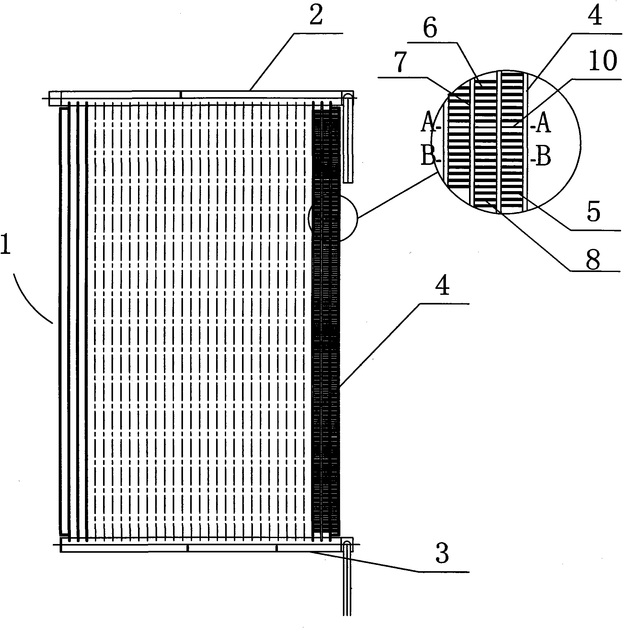
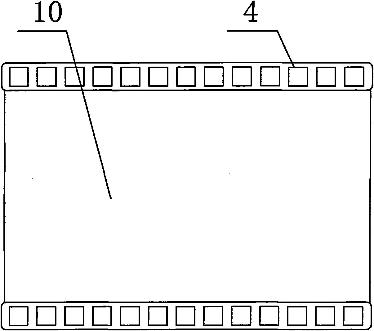
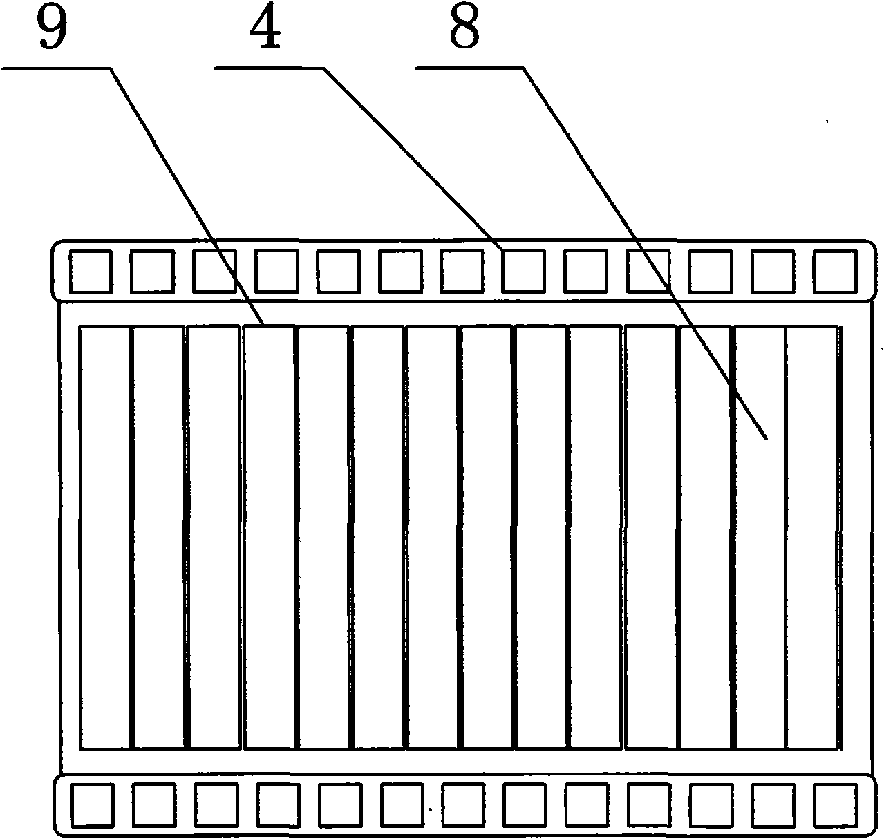
[0025] The parallel flow heat exchanger involved in the present invention can be applied to indoor and outdoor units of an air conditioner as a refrigerant heat exchanger for cooling and heating. Since the main purpose of the present invention is to optimize the drainage of parallel flow heat exchangers, only discuss its use as an evaporator in this patent, such as figure 1 As shown, the heat exchanger 1 is a flat plate type, including an upper header 2 on the upper part, a lower header 3 on the lower part, and a plurality of connecting flat tubes 4 between the upper and lower headers 2 and 3, Between the flat tubes 4, there are rectangular arrangements (as attached) Figure 9d Shown) fin 5. Air enters one side of the heat exchanger and exits the other, at figure 1 The middle is the blowing direction from the surface of the paper. In Example 1, the projection line of the working section of the water-permeable fin on the flat tube is perpendicular to the edge of the air inlet...

Embodiment 2

[0030] The main difference between the second embodiment and the first embodiment is that the number of fins in the impermeable section is more than one. The numerical value of the punched sheet of each group in the embodiment two is 8, namely Figure 4 The water-permeable section 14 includes 8 punched sheets, and the water-impermeable section 15 below it includes 2 water-impermeable fins 10 . The second water-impermeable fin 10 is to avoid the damage of the single water-impermeable fin in the first embodiment and make the drainage function invalid, so each water-impermeable section 15 can be provided with 2-3 water-impermeable fins, Together to complete the task of draining condensate.

Embodiment 3

[0032] The main difference between the third embodiment and the first embodiment is that the number of perforated pieces in the permeable section of the third embodiment is changed. Such as Figure 5 As shown, when the number of water-permeable fins in the water-permeable section is different, set n1, n2, n3..., n1=445 of the uppermost layer in Embodiment 3, according to each passing through a water-permeable fin segment, The ratio n is reduced by 40, then n2=405, n3=365. An impermeable fin section is arranged under each water-permeable fin section, and the water-impermeable wing section includes 1 to 3 fins. The number of working sections of the total fins in Example 3 is 2282, and n7 is 205. Due to the high temperature in the upper part of the heat exchanger, the amount of condensed water produced is less than that in the lower part of the heat exchanger with a lower temperature. If the number of punched plates in each permeable section is consistent, the amount of condens...


PUM


Abstract

The invention relates to a heat exchanger for improving drainage performance, which comprises an upper collecting pipe, a lower collecting pipe and a plurality of flat pipes, wherein the flat pipes are vertically connected between the upper collecting pipe and the lower collecting pipe; a plurality of fins are arranged between the adjacent flat pipes; the fins are divided into permeable fins and watertight fins; the permeable fins form a plurality of permeable sections; the watertight fins form a plurality of watertight sections; and the permeable sections and the watertight sections are distributed at intervals. By distributing the watertight fins among the permeable fins at intervals, condensate water collected by the seam flushing fins at the watertight fins can be drained out of the heat exchanger, and the amount of the condensate water flowing through the permeable fins at the lower part is reduced. Meanwhile, by adopting the watertight fins with convex edges, the intercepted condensate water more favorably drops from the fins by the convex edges, and the fins at the lower part is not influenced. Furthermore, the fins are inclined relative to the windward side and are beneficial to the drainage of the condensate water, thereby improving the drainage performance of the heat exchanger so as to improve the heat exchange performance of the heat exchanger.

Description

technical field [0001] The invention relates to a heat exchanger, in particular to a parallel flow heat exchanger capable of improving the performance of discharging condensed water. Background technique [0002] When the parallel flow heat exchanger is used as an evaporator or heat pump outside the outdoor heat exchanger, condensed water will be generated on the surface. In order to improve the performance of the heat exchanger to discharge condensed water, the headers are usually set horizontally and the flat tubes are installed vertically. Between the headers, there are fins between the headers. The fins generally include a working section with a straight line section and a connecting section connecting the working section, and the heat exchange is generally realized through the working section, so it is generally called Fin refers to the working section of the fin. Just because the header is located on the upper and lower sides, the working section between the fins and ...

Claims


Application Information

Patent Timeline
IPC IPC(8): F25B39/00F28F1/10F28F17/00
Inventor 刘阳佐藤宪一郎李强
Owner GD MIDEA AIR-CONDITIONING EQUIP CO LTD
Why Eureka
Try Eureka