Touch sensing device and touch sensing method

A sensing device and touch technology, applied in the field of touch sensing and touch sensing devices, can solve problems such as misjudgment of touch events

Active Publication Date: 2011-01-26
AU OPTRONICS CORP
View PDF4 Cites 18 Cited by
  • Summary
  • Abstract
  • Description
  • Claims
  • Application Information

AI Technical Summary

Problems solved by technology

Then, when the in-cell touch liquid crystal panel 300 performs touch sensing, it is easy to misjudge the touch event due to the unevenness of the sensing gap.

Method used


Image

  • Touch sensing device and touch sensing method
  • Touch sensing device and touch sensing method
  • Touch sensing device and touch sensing method

Examples


no. 1 example

[0086] Figure 4It is a schematic diagram of an in-cell touch liquid crystal panel adopting the touch sensing device of the present invention. exist Figure 4 Among them, the embedded touch liquid crystal panel includes a liquid crystal panel 402, a plurality of capacitive touch sensors (as shown in 404), a plurality of sensing signal reading lines (as shown in 406) and a rear end processing circuit 408 . Wherein, the capacitive touch sensors 404 and the back-end processing circuit 408 are the main components of the touch sensing device. Each capacitive touch sensor 404 is electrically coupled to the back-end processing circuit 408 through a sensing signal readout line 406 .

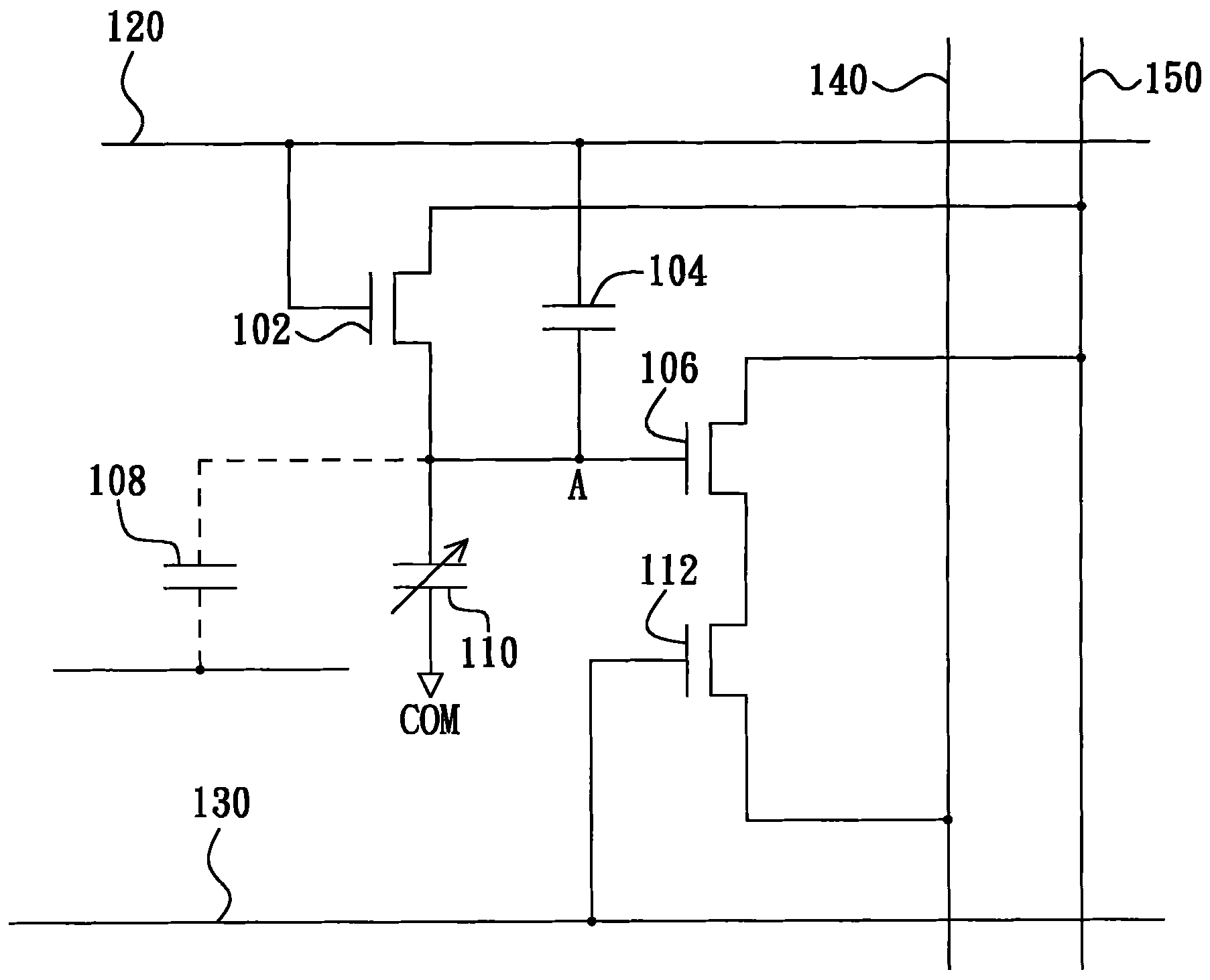
[0087] The aforementioned capacitive touch sensors 404 are disposed in the liquid crystal panel 402 . Each capacitive touch sensor 404 has a touch sensing capacitor (not shown, described in detail later), and each touch sensing capacitor has two electrodes. Each capacitive touch sensor 404 determine...

no. 2 example

[0104] The difference between this embodiment and the first embodiment lies in that among any two rows of capacitive touch sensors 404 in the liquid crystal panel 402 of this embodiment, one row of capacitive touch sensors 404 uses the aforementioned capacitance The hardware architecture of the type touch sensor 500 , while the other row of capacitive touch sensors 404 uses redundant capacitive touch sensors 500 .

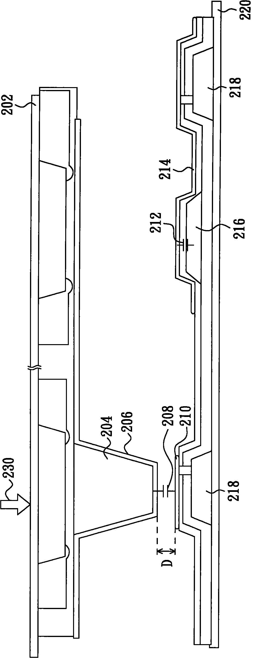
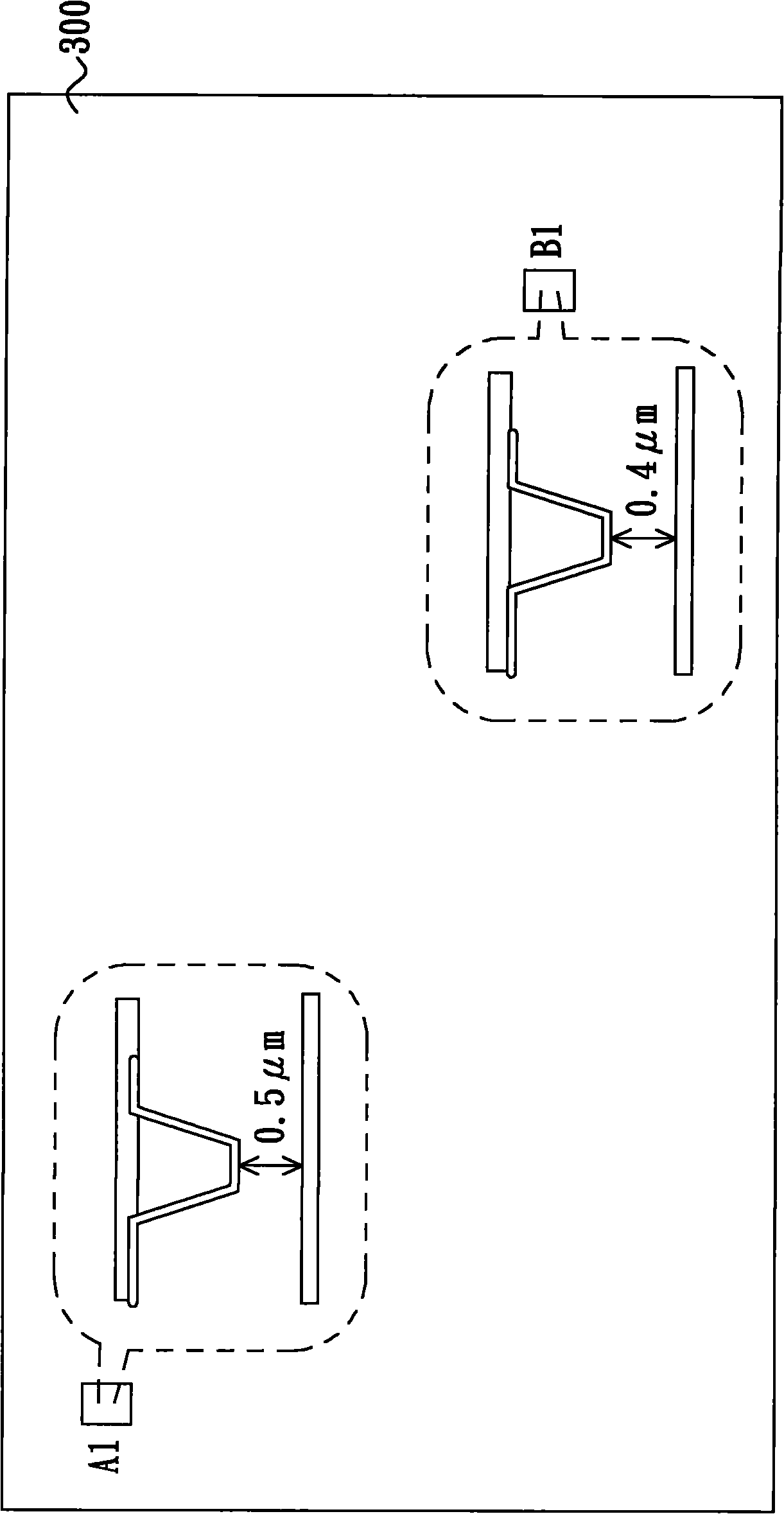
[0105] The so-called redundant capacitive touch sensor 500 is obtained by fixing the distance between the two electrodes of the touch sensing capacitor 506 of the aforementioned capacitive touch sensor 500, that is, the aforementioned capacitive touch sensor The sensing gap of the touch sensor 500 is fixed. Therefore, the redundant capacitive touch sensor 500 outputs a certain output current no matter whether the user touches it or not. The touch event judging method of this embodiment will be further described below.

[0106] please refer again Figure 11 , ass...

no. 3 example

[0108] The difference between this embodiment and the first embodiment lies in that among any two rows of capacitive touch sensors 404 in the liquid crystal panel 402 of this embodiment, one row of capacitive touch sensors 404 uses the aforementioned capacitance type touch sensor 500 , while another row of capacitive touch sensors 404 uses modified capacitive touch sensor 500 . The so-called modified capacitive touch sensor 500 is to use the gate of the transistor 504 in the aforementioned capacitive touch sensor 500 and the reference capacitor 502 to receive the scanning pulse signal G n One ends of the two are electrically connected to each other so as to receive the same scan pulse signal. That is to say, the gate of the transistor 504 and the reference capacitor 502 are used to receive the scan pulse signal G n The pulse size of the scan pulse signal received at one end of the two must be the same and have the same phase.

[0109] The gate of the transistor 504 and the r...


PUM


Abstract

The invention relates to a touch sensing device and a touch sensing method. The touch sensing device comprises a plurality of capacitor type touch sensors and a rear end processing circuit, wherein each capacitor type touch sensor is provided with a touch sensing capacitor, and each capacitor type touch sensor decides the magnitudes of output currents according to the distance between two electrodes of the touch sensing capacitors; the rear end processing circuit is used for respectively carrying out integral operations on the output currents so as to obtain a plurality of voltage values; therear end processing circuit is also used for judging whether a touch situation happens or not according to the voltage difference of two voltage values corresponding to two capacitor type touch sensors so as to further decide whether to calculate the coordinates of the touch position or not; and the change of each voltage value has a linear relation with the change of the distance between two electrodes of a corresponding touch sensing capacitor.

Description

technical field [0001] The present invention relates to the technology in the touch field, and in particular relates to a touch sensing device and a touch sensing method. Background technique [0002] The known in-cell touch (in-cell touch) liquid crystal panel often uses a touch sensing device composed of a capacitive touch sensor (described in detail) and a back-end processing circuit (described in detail), wherein The capacitive touch sensor is used to sense the user's touch, and the back-end processing circuit judges the touch event (touch event) according to the output signal of the capacitive touch sensor. However, the known in-cell touch LCD panel often misjudges the touch event, please refer to the following description. [0003] figure 1 That is, an equivalent circuit of a known capacitive touch sensor and its coupling relationship are shown. Please refer to figure 1 , the capacitive touch sensor is composed of a transistor 102 , a reference capacitor 104 , a tr...

Claims


Application Information

Patent Timeline
Patent Type & Authority Applications(China)
IPC IPC(8): G02F1/133G06F3/044
Inventor 刘子维黄雪瑛
Owner AU OPTRONICS CORP
Why Eureka
Try Eureka