Zero sequence current mutual inductor

A zero-sequence current, transformer technology, applied in the direction of inductors, transformers/inductor coils/windings/connections, voltage/current isolation, etc., can solve the scratching damage of insulating tapes, the difficulty of conducting copper bars, and the difficulty of wearing transformers It can save space, shorten working hours, and avoid passing through and arranging processes.

Active Publication Date: 2011-01-26
EATON HUINENG LOW-VOLTAGE ELECTRICAL (JIANGSU) CO LTD
View PDF7 Cites 6 Cited by
  • Summary
  • Abstract
  • Description
  • Claims
  • Application Information

AI Technical Summary

Problems solved by technology

Due to the limited internal space of the leakage circuit breaker, the volume of the main body of the transformer is also limited, so the shape of the conductive copper bar is bent, and it is very difficult to actually install the conductive copper bar, especially for the four-phase transformer. At the same time, due to the main circuit structure of the zero-sequence current transformer, the three-phase conductive copper bars (or four-phase) need to be insulated from each other. The traditional method is to wrap insulating tape on the surface of the conductive copper bars, which is very easy to cause If the insulating tape is scratched and damaged, it is necessary to re-wrap the insulating tape and re-thread the row, which increases the workload; the conductive copper row behind the traditional zero-sequence current transformer also takes up space at the connection with the thermal element of the trip unit

Method used


Image

  • Zero sequence current mutual inductor
  • Zero sequence current mutual inductor
  • Zero sequence current mutual inductor

Examples


Embodiment Construction

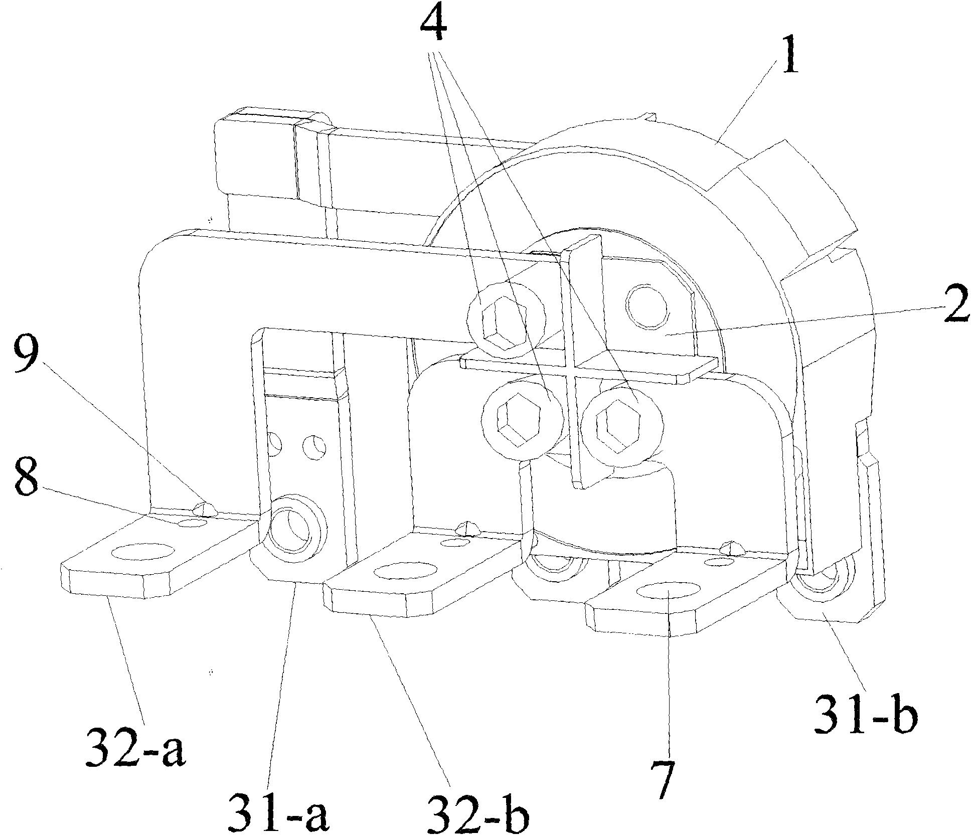
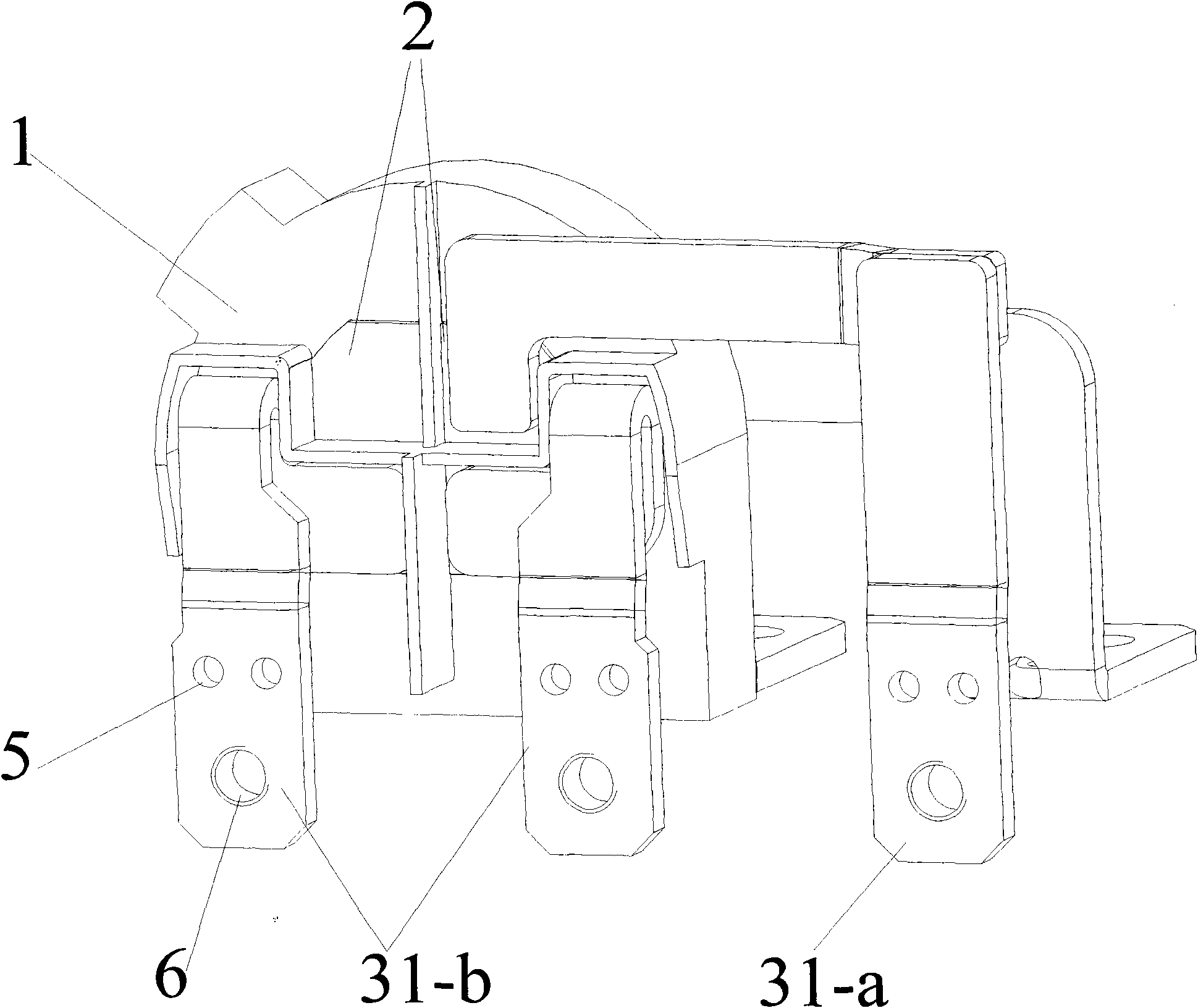
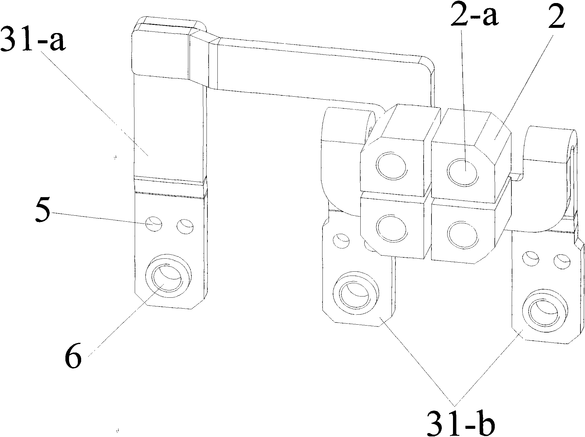
[0028] The present invention will be described in further detail below in conjunction with the accompanying drawings and specific embodiments.

[0029] like Figure 1 to Figure 7 As shown, 1 is the body of the zero-sequence current transformer; 11 is the front separation area structure of the main body of the transformer, 11-a is the first area on the front, 11-b is the second area on the front, 11-c is the third area on the front, 11 -d is the fourth area on the front; 12 is the partition structure on the back of the main body of the transformer, 12-a is the first area on the back, 12-b is the second area on the back, 12-c is the third area on the back, and 12-d is the back The fourth area; 2 is a conductive copper rod, 2-a is a threaded hole; 31-a is the first back conductive copper row, 31-b is the second back conductive copper row, 32-a is the first front conductive copper row, 32-b is the second front conductive copper bar; 4 is the screw, 5 is the first hole on the back...


PUM


Abstract

The invention relates to a zero sequence current mutual inductor. A separated region is positioned in the center of the zero sequence current mutual inductor body (1), so that the zero sequence current mutual inductor body (1) is divided into a front separated region structure (11) of the mutual inductor body and a back separated region structure (12) of the mutual inductor body; the front separated region structure (11) of the mutual inductor body and the back separated region structure (12) of the mutual inductor body have a cross raised structure respectively, and are both divided into four separated regions, and a conductive copper rod (2) and back conductive copper bars are integrated into a whole; the conductive copper rod (2) is arranged in the central separated region of the zero sequence current mutual inductor body (1); a threaded hole (2-a) is formed on the conductive copper rod (2); a screw (4) passes through the zero sequence current mutual inductor, so that front conductive copper bars are connected with the back conductive copper bars welded on the conductive copper rod (2); and the front conductive copper bars are positioned on the front separated region structure (11) of the mutual inductor body, and the back conductive copper bars are positioned on the back separated region structure (12) of the mutual inductor body.

Description

technical field [0001] The invention relates to a zero-sequence current transformer, in particular to a zero-sequence current transformer for a residual current circuit breaker. Background technique [0002] In the three-phase low-voltage power supply system, when the load and insulation are symmetrical, the vector sum of the three-phase currents is equal to zero. If the insulation of a certain phase of the three-phase power grid is damaged or leakage or grounding occurs, the vector sum of the three-phase currents is not zero, and this current is generally called zero-sequence current. The zero-sequence current transformer is used to measure the magnitude of the zero-sequence current. Put the transformer on the outside of the conductive rod, that is, the three-phase current passes through the iron core of the zero-sequence current transformer as its primary side (the primary side of the primary wire), and according to the requirements of sensitivity and angular characterist...

Claims


Application Information

Patent Timeline
Patent Type & Authority Applications(China)
IPC IPC(8): H01F38/28H01F38/30H01F27/40H01F27/29G01R15/18
Inventor 陈咸任飞胡义琴严丽君
Owner EATON HUINENG LOW-VOLTAGE ELECTRICAL (JIANGSU) CO LTD
Why Eureka
Try Eureka