PWM (Pulse Width Modulation) control circuit

A control circuit, pulse width modulation technology, applied in the direction of pulse duration/width modulation, etc., can solve the problems of modulation error increase, modulation error, etc.

Inactive Publication Date: 2011-01-26
HUAZHONG UNIV OF SCI & TECH
View PDF4 Cites 2 Cited by
  • Summary
  • Abstract
  • Description
  • Claims
  • Application Information

AI Technical Summary

Problems solved by technology

[0007] The present invention provides a pulse width modulation control circuit, which solves the problem of modulation error in the existing pulse width modulation control circuit and the increase of modulation error with the increase of the frequency of the reference signal. Negative modulation wave for modulation to improve modulation and control accuracy

Method used


Image

  • PWM (Pulse Width Modulation) control circuit
  • PWM (Pulse Width Modulation) control circuit
  • PWM (Pulse Width Modulation) control circuit

Examples


Embodiment Construction

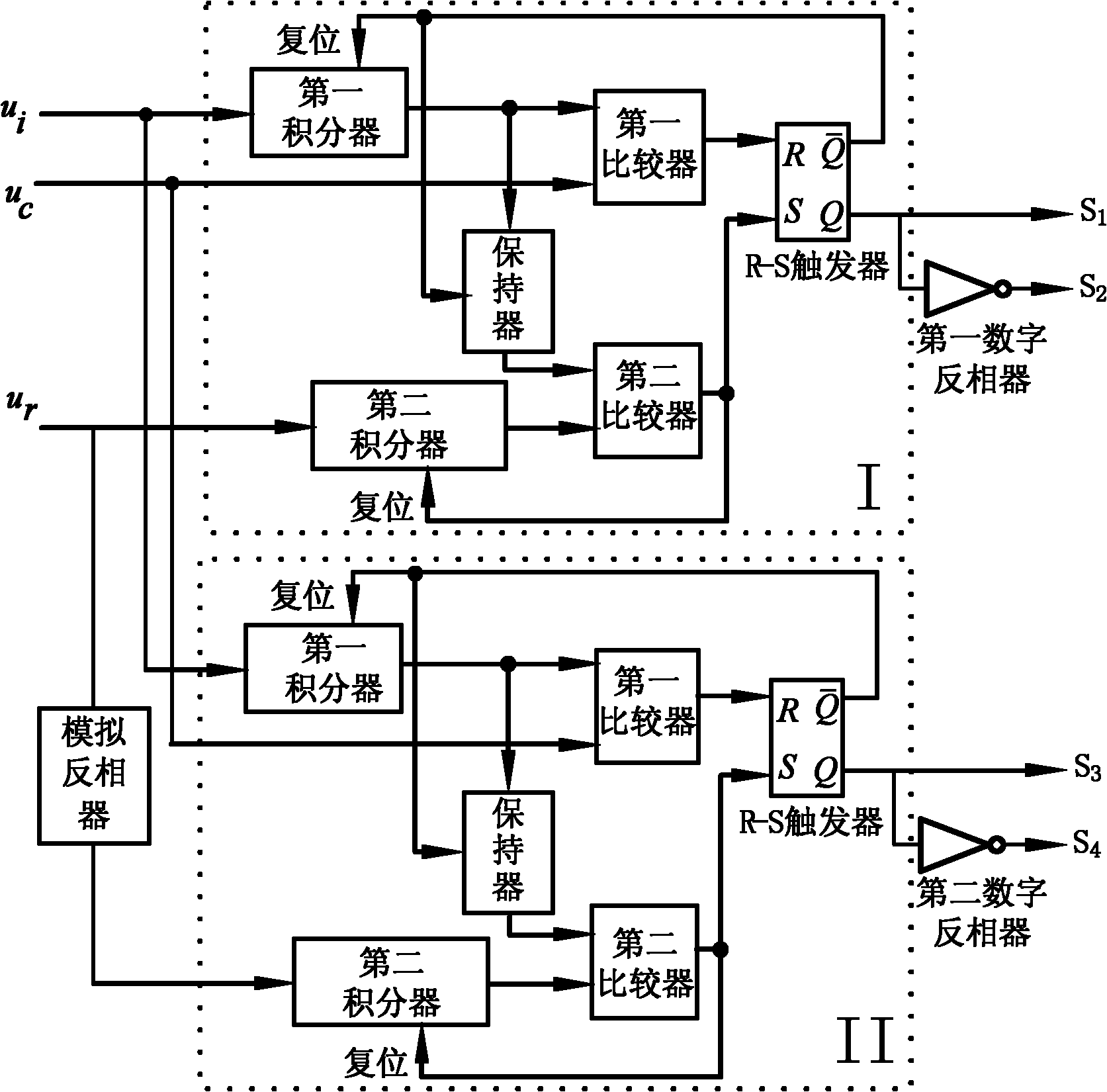
[0067] Such as figure 1 As shown, the present invention includes a first reset integration module I, a second reset integration module II, an analog inverter, a first digital inverter and a second digital inverter.

[0068] The first reset integration module I and the second reset integration module II have the same structure, and are each composed of a first integrator, a second integrator, a holder, a first comparator, a second comparator and an R-S flip-flop;

[0069] The DC voltage signal input terminals of the first reset integration module I and the second reset integration module II are connected together to input the DC voltage signal u i ; The comparison signal input ends of the first reset integration module I and the second reset integration module II are connected together, and the comparison signal u is input c ;

[0070] The first reset integration module I controls the reference signal input terminal to input the control reference signal u r ;Control referenc...


PUM


Abstract

The invention relates to a PWM (Pulse Width Modulation) control circuit belonging to a power electronic control circuit and solving the problems of modulation error and error increase with the rise of a reference signal existing in the PWM control circuit. The PWM control circuit comprises a first reset integral module, a second reset integral module, an analog inverter, a first digital inverter and a second digital inverter, wherein either the first reset integral module or the second reset integral module comprises a first integrator, a second integrator, a retainer, a first comparator, a second comparator and an R-S (Reset-Set) trigger. The invention has the advantages of simple circuit, convenient implementation and convenient integration, combines PWM and control and improves the quality of an output waveform. In an impulse meaning, no error is accumulated between an output signal and a control reference signal among various switching cycles, and the output signal impulse and the control reference signal impulse are identical in each switching cycle. The invention can keep stable switching output when a switching input signal fluctuates in a large range, greatly improves the control accuracy and the dynamic tracking capability and can be used for the PWM wave generation and the system control of various switching power supply converters.

Description

technical field [0001] The invention belongs to a power electronic control circuit, in particular to a pulse width modulation control circuit, which is used for PWM wave generation and system control of various switching power converters with positive and negative bidirectional waveform complementary modulation. Background technique [0002] At present, a triangle wave or a sawtooth wave is widely used to modulate the reference signal to generate a pulse width modulated wave. The main disadvantage of this modulation method is that the modulation error is large and the impulse cannot be equal. In order to improve the anti-interference ability of the system and achieve stable output, from the control point of view, the typical control method currently used is to introduce multi-loop negative feedback, specifically, the feedback signal and the feedforward signal are sent to the controller at the same time to generate a modulation signal, and then used The modulation signal is ...

Claims


Application Information

Patent Timeline
Patent Type & Authority Applications(China)
IPC IPC(8): H03K7/08
Inventor 李承杨红权
Owner HUAZHONG UNIV OF SCI & TECH
Why Eureka
Try Eureka