Knee joint including manual lock mechanism and artificial thigh

A technology of locking mechanism and coupler, applied in artificial legs, medical science, prosthesis, etc., can solve the problems of difficult to realize compact structure of knee coupler and prosthesis, many components, complex structure, etc.

Active Publication Date: 2011-01-26
NABLESCO CORP
View PDF13 Cites 6 Cited by
  • Summary
  • Abstract
  • Description
  • Claims
  • Application Information

AI Technical Summary

Problems solved by technology

However, the previous manual locking mechanism has a complex structure and many components, and a new mechanism that fixes the wire under tension is required.
Therefore, it is difficult to realize the compact structure of the knee coupler and the prosthesis, and there is also room for improvement in appearance

Method used


Image

  • Knee joint including manual lock mechanism and artificial thigh
  • Knee joint including manual lock mechanism and artificial thigh
  • Knee joint including manual lock mechanism and artificial thigh

Examples


Embodiment Construction

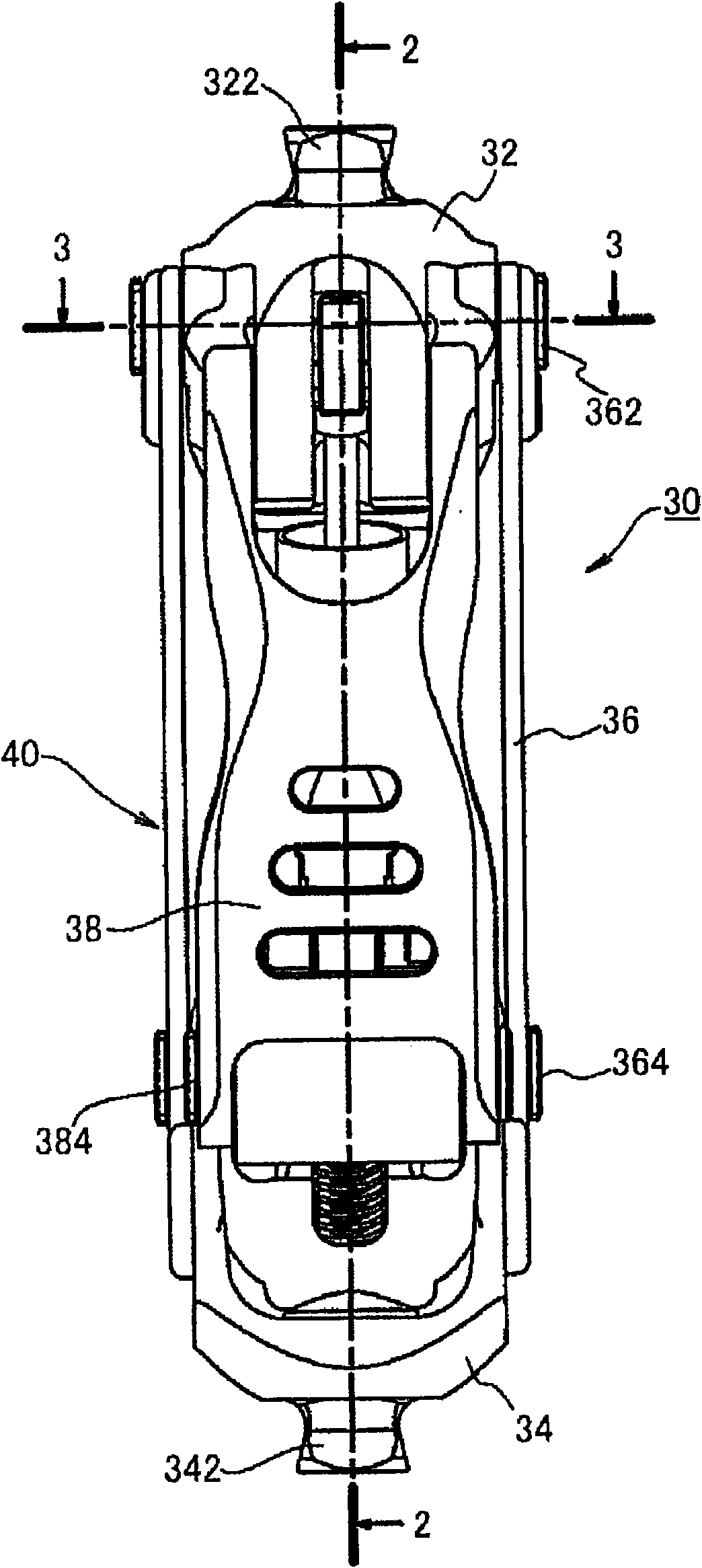
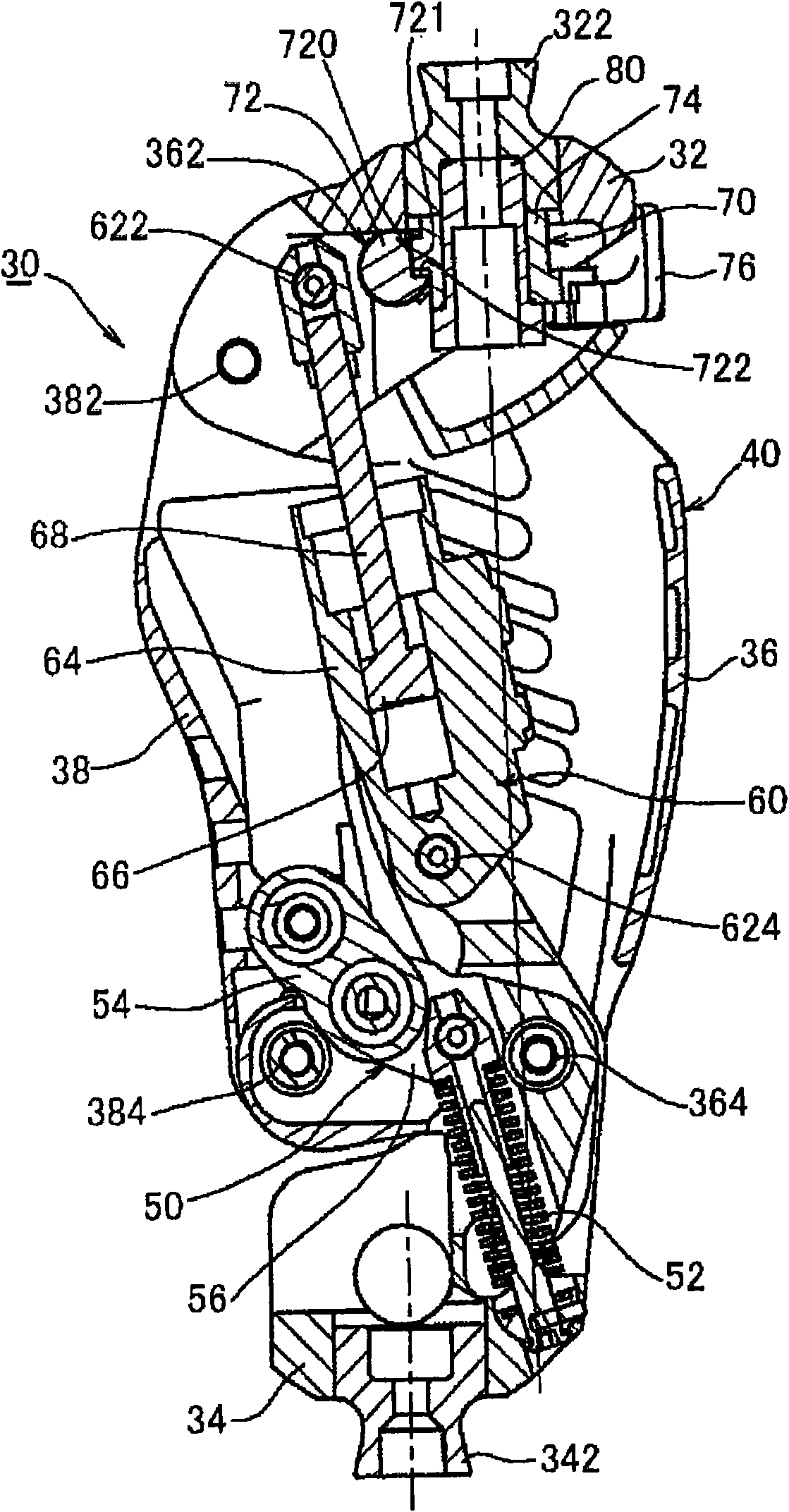
[0067] Figure 1 ~ Figure 3 This is the first embodiment of applying the present invention to a multi-axis knee joint. The knee coupler 30 of the first embodiment includes an upper member 32 located on the upper side of the knee, and a lower member 34 located on the lower side of the knee and swingably connected to the upper member 32 to allow the knee to bend. The upper member 32 integrally supports the positioning block 322 at the upper central part. The positioning block 322 is a part to which a sleeve (not shown) is attached, and supports the load of the prosthetic user by inserting the thigh of the sleeve. On the other hand, another positioning block 342 is also provided in the lower center of the lower member 34. The positioning block 342 is a part where a foot member for supporting the foot is installed. Thus, the knee coupling 30 constitutes the main part of the thigh prosthesis.

[0068] The multi-axis connecting device 40 connects the upper member 30 and the lower me...


PUM


Abstract

Technology of a manual lock mechanism for manually switching over oscillation of an upper member and a lower member at a knee joint between locked and unlocked conditions. A simple structure of the manual lock mechanism and size reduction of the knee joint or an artificial leg are aimed at in particular. For these purposes, one of oscillating shafts for swingably coupling the upper member and thelower member is regulated. Therefore, the manual lock mechanism includes the oscillating shaft including an irregular part and a lock member for regulating the movement of the oscillating shaft. The lock member can be switched over between the locked condition of being in contact with the irregular part of the shaft and the unlocked condition of being separate from the irregular part. When locked, force from the oscillating shaft is applied as compression load in the longitudinal direction of the lock member.

Description

Technical field [0001] The present invention relates to a knee joint capable of manually switching an upper member located above the knee and a lower member located below the knee into a swingable non-locking state or a non-swinging locked state with the knee extended The thigh prosthesis of the knee coupling particularly relates to a technology that can effectively make the manual locking mechanism for switching between the unlocked state and the locked state compact. Background technique [0002] The knee coupling functions as a knee joint capable of swinging the upper member and the lower member. A typical representative of a prosthetic limb with this kind of knee joint is a thigh prosthetic limb. For prosthetic limbs with knee couplings, in order to effectively perform swinging motions, resistance generating devices such as pneumatic cylinders, hydraulic cylinders, or spring cylinders are generally provided. In order to achieve the miniaturization or compact structure of th...

Claims


Application Information

Patent Timeline
Patent Type & Authority Applications(China)
IPC IPC(8): A61F2/64
CPCA61F2002/745A61F2/642A61F2/68A61F2002/6854A61F2002/748A61F2002/5072A61F2002/747A61F2/74A61F2/748
Inventor 奥田正彦中矢贺章
Owner NABLESCO CORP
Why Eureka
Try Eureka