
Jet flow-driven blood vessel robot
A robot and blood vessel technology, applied in the field of blood vessel robots, can solve problems such as unsmooth appearance, complex structure, damage to blood vessel walls, etc., and achieve the effect of smooth appearance and flexible movement
- Summary
- Abstract
- Description
- Claims
- Application Information
AI Technical Summary
Problems solved by technology
Method used
Image

Examples
Embodiment Construction
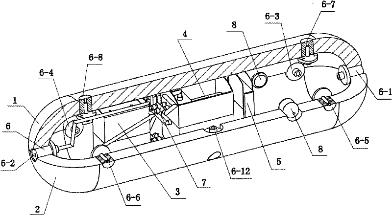
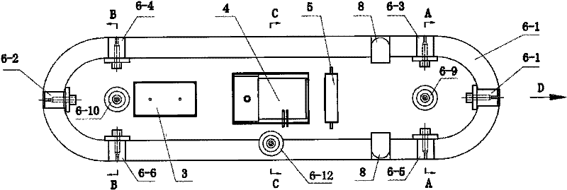
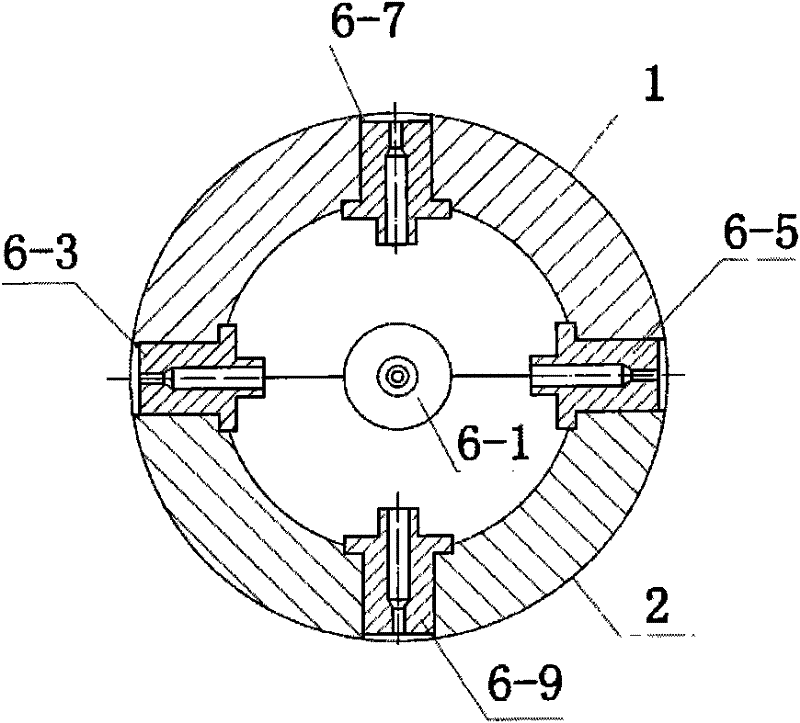
[0027] see Figure 1 to Figure 6 , the jet-driven vascular robot of this embodiment is composed of a capsule-shaped casing, a liquid flow control device with blood as a medium, a wireless receiving control block 5, and an operating device 8 inside the casing; wherein, the capsule-shaped casing is composed of The upper half shell 1 and the lower half shell 2 are buckled together, and the working device 8 is a miniature CCD camera.
[0028] see Figure 1 to Figure 6 , The liquid flow control device consists of a variable pump 4, 12 suction nozzles 6 and 24 two-position two-way solenoid valves 7. Wherein, the suction nozzle 6 is a cylinder, and a through hole is arranged axially in the body, one end of the through hole is an entrance, and the other end shrinks inwardly to form a tiny suction nozzle; the entrance and exit of each suction nozzle 6 are parallel There are two pipelines respectively connected in series with a two-position two-way solenoid valve 7, one of which is co...
PUM
 Abstract
Description
Claims
Application Information