Laser tailor-welded weld rolling preforming combined pressing wheel

A technology of preforming and rolling wheels, which is applied in laser welding equipment, welding equipment, metal processing equipment, etc., can solve the problems of increasing equipment cost, reducing equipment operation efficiency, and the edge of steel plate cannot be accurate and straight, so as to eliminate the welding seam Clearance, increased rigidity, and simple structure

Inactive Publication Date: 2013-06-12
SHENYANG INST OF AUTOMATION - CHINESE ACAD OF SCI
View PDF6 Cites 2 Cited by
  • Summary
  • Abstract
  • Description
  • Claims
  • Application Information

AI Technical Summary

Problems solved by technology

[0002] In order to meet the quality requirements of laser tailor welding, the gap between two welded steel plates should be less than 0.05mm, but due to the error of the existing shearing machine and the deformation of the plate itself, the edge of the sheared steel plate cannot be accurately straightened , the accuracy of the existing domestic shearing machine is about 0.1mm / m, which cannot meet the welding requirements of long welded plates at all
At present, the assembly quality of the edge of the steel plate is mainly improved by grinding the edge of the plate, laser cutting and extrusion, but these methods not only greatly increase the cost of the equipment, but also reduce the operating efficiency of the equipment

Method used


Image

  • Laser tailor-welded weld rolling preforming combined pressing wheel
  • Laser tailor-welded weld rolling preforming combined pressing wheel
  • Laser tailor-welded weld rolling preforming combined pressing wheel

Examples


Embodiment Construction

[0018] The present invention will be described in further detail below in conjunction with the accompanying drawings.

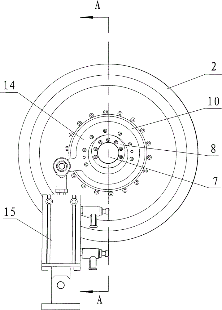
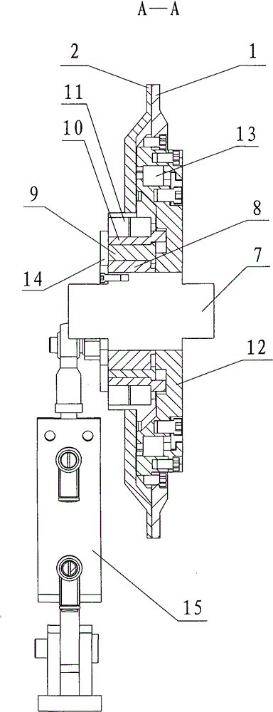
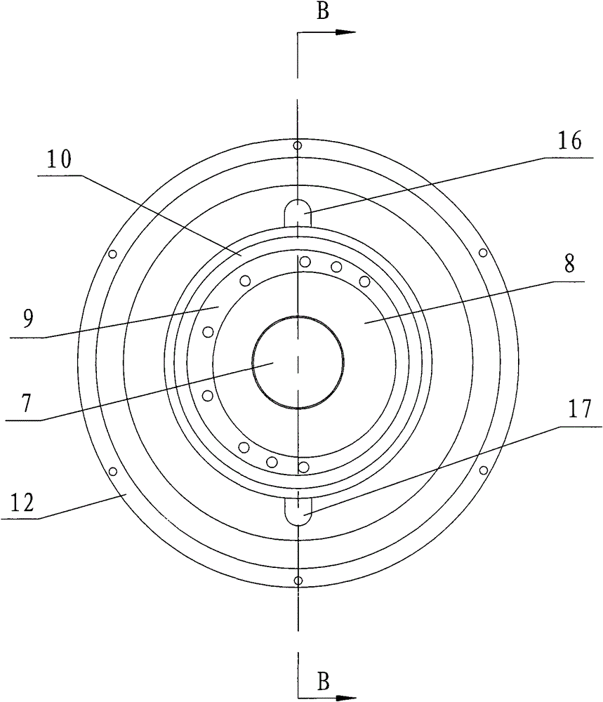
[0019] Such as Figure 1~4 As shown, the present invention includes rolling wheel 1, pressing wheel 2, pressing wheel shaft 7, inner layer eccentric sleeve 8, outer layer eccentric sleeve 9, rotary sleeve 10, rear end cover 12, connecting cover 14 and drive cylinder 15, pressing The wheel shaft 7 is installed on the laser tailor welding machine. One side of the pressure wheel shaft 7 is set with an inner eccentric sleeve 8, an outer eccentric sleeve 9 and a rotary sleeve 10 in sequence from the inside to the outside, that is, the inner eccentric sleeve 8 is set on the pressure wheel shaft. 7, the outer eccentric sleeve 9 is set on the inner eccentric sleeve 8, and the outer eccentric sleeve 9 is provided with a rotary sleeve 10, and the other side of the pressing wheel shaft 7 is provided with a rear end cover 12; the rolling wheel 1 passes The rolling wheel...


PUM


Abstract

The invention relates to laser tailor-welded weld rolling preforming equipment, in particular to a laser tailor-welded weld rolling preforming combined pressing wheel. The combined pressing wheel comprises a rolling wheel, a compaction wheel, a pressing wheel shaft and a driving cylinder, wherein one end of the driving cylinder is arranged on a laser tailor-welded machine, while the other end is connected with a crank sliding mechanism sleeved on one side of the pressing wheel shaft; the compaction wheel is sleeved on one side of the pressing wheel shaft and connected with a sliding block in the crank sliding mechanism and can move up and down, to and fro under the drive of the sliding block; and the rolling wheel is sleeved on the other side of the pressing wheel shaft. The edge of a thick steel plate is rolled by using the rolling wheel on the thick steel plate side so that weld gaps are eliminated by plastic deformation of the thick steel plate, and a thin steel plate is compacted by using the compaction wheel on the thin steel plate side so as to avoid deformation of the thin steel plate during rolling; the rolling wheel and the compaction wheel are connected on the same pressing wheel shaft through an eccentric mechanism so as to improve the rigidity of the pressing wheel shaft; and the rolling wheel and the compaction wheel have relative movement in the vertical direction so as to meet the requirement of different plate thickness differences.

Description

technical field [0001] The invention relates to laser tailor welding seam preforming equipment, in particular to a laser tailor welding seam rolling preforming combined pressing wheel. Background technique [0002] In order to meet the quality requirements of laser tailor welding, the gap between two welded steel plates should be less than 0.05mm, but due to the error of the existing shearing machine and the deformation of the plate itself, the edge of the sheared steel plate cannot be accurately straightened , the accuracy of the existing domestic shearing machine is about 0.1mm / m, which cannot meet the welding requirements of long welded plates at all. At present, the assembly quality of the steel plate edge is mainly improved by grinding the edge of the plate, laser cutting and extrusion, but these methods not only greatly increase the cost of the equipment, but also reduce the operating efficiency of the equipment. Contents of the invention [0003] In order to solve ...

Claims


Application Information

Patent Timeline
Patent Type & Authority Patents(China)
IPC IPC(8): B23K26/42B23K26/24B23K26/70
Inventor 徐志刚王军义刘勇李锋赵明扬
Owner SHENYANG INST OF AUTOMATION - CHINESE ACAD OF SCI
Why Eureka
Try Eureka