Catapult used on aircraft carrier

A technology of aircraft carrier and catapult, which is applied in the direction of launching/dragging transmission device, etc. It can solve the problems of high cost of operation and maintenance, reduced ejection force of catapult, and reduced rotation speed, etc., and achieves low ejection cost, high take-off speed, and strong explosive force Effect

Inactive Publication Date: 2011-02-02
吴炳发
View PDF6 Cites 8 Cited by
  • Summary
  • Abstract
  • Description
  • Claims
  • Application Information

AI Technical Summary

Problems solved by technology

The main disadvantages of steam catapults are: the system is huge, the cost of operation and maintenance is high, and it also needs to consume a lot of fresh water
The flywheel of the catapult is fixedly connected to the transmission shaft, and the rotation of the transmission shaft drives the rotation of the flywheel. The flywheel relies on inertia to maintain rotation. When the high-speed rotating flywheel is loaded with carrier-based aircraft and other loads, the rotation speed of the flywheel will be greatly reduced. Therefore, the ejection force of the catapult will be reduced

Method used


Image

  • Catapult used on aircraft carrier
  • Catapult used on aircraft carrier
  • Catapult used on aircraft carrier

Examples


Embodiment Construction

[0022] The present invention will be further described in detail below in conjunction with the accompanying drawings and embodiments.

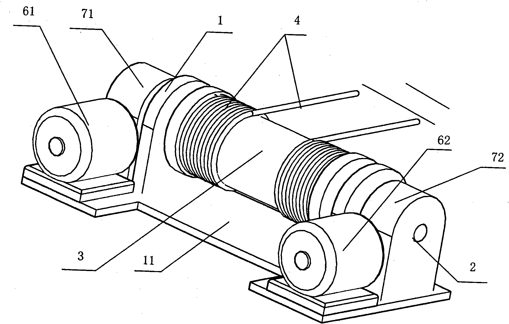
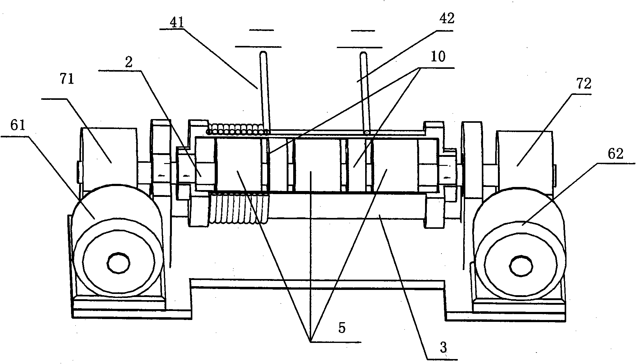
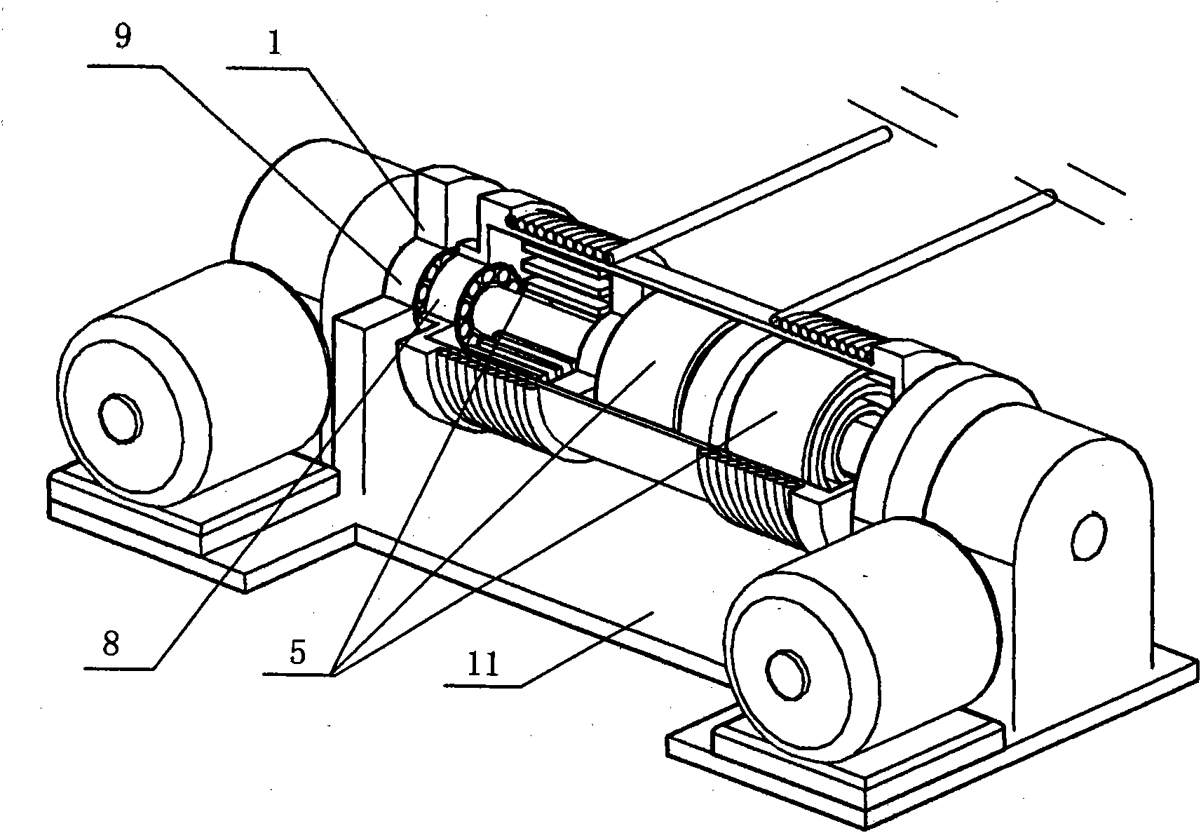
[0023] A catapult for an aircraft carrier, comprising a power system and a seat frame 1, a rotating shaft 2 is mounted on the seat frame 1, a cylinder 3 is arranged outside the rotating shaft 2, and at least one traction cable is wound around the cylinder 3 4. At least one spring-type steel plate 5 is arranged between the rotating shaft 2 and the inner wall of the cylinder 3 , the traction cable 4 is connected with a tractor (not shown in the figure), and the power system is connected with the rotating shaft 2 .

[0024] The power system includes two motors and two reducers, which are respectively the first motor 61, the second motor 62, the first reducer 71 and the second reducer 72, and the first motor 61 is connected to the rotating shaft 2 through the first reducer 71. One end is connected, and the second motor 62 is connected with the oth...


PUM


Abstract

The invention discloses a catapult used on an aircraft carrier, comprising a power system and a seat frame, wherein, a rotating shaft is arranged on the upper frame of the seat frame; a cylinder is arranged outside the rotating shaft; at least one curly hair strip-shaped steel plate is arranged between the rotating shaft and the inner wall of the cylinder; a traction steel cable is wound outside the cylinder; a tractor is connected on the traction steel cable; and the power system is connected with the rotating shaft. The catapult has the characteristic of strong moment explosive force, leadsthe launching distance of an object to be far, can be rapidly reused; in each launching, the common electric power is only needed to lead the power system to tightly twist the spring-type steel plate, and the launching cost is low.

Description

technical field [0001] The invention relates to a catapult, in particular to a catapult used on an aircraft carrier. Background technique [0002] At present, the take-off methods of carrier-based aircraft on aircraft carriers mainly include steam-type catapults, which use steam as power, and the cylinder piston drives the towing hook to pull the aircraft to accelerate take-off. The main disadvantages of the steam catapult are: the system is huge, the cost of operation and maintenance is high, and it also needs to consume a large amount of fresh water. The patent application No. 201010110019.3 published on August 18, 2010 is titled "A Catapult and Launching Method for Accelerated Flywheel Accelerated Aircraft". Its structure is composed of a power machine, a clutch, a flywheel, a transmission shaft, a traction winch and The rope-laying winch is composed of the traction winch and the flywheel are set on the transmission shaft, the flywheel and the transmission shaft are fixe...

Claims


Application Information

Patent Timeline
IPC IPC(8): B64F1/06
Inventor 吴炳发
Owner 吴炳发
Why Eureka
Try Eureka