
Bonding equipment

一种贴合设备、贴合装置的技术,应用在仪器、化学仪器和方法、电气元件等方向,能够解决影响设备利用率贴合的效率等问题

Active Publication Date: 2011-02-02
JINCHENG FUTAIHUA PRECISION ELECTRONICS CO LTD
View PDF0 Cites 11 Cited by
  • Summary
  • Abstract
  • Description
  • Claims
  • Application Information

AI Technical Summary

Problems solved by technology

However, because the time for tearing the film is shorter than the time for laminating the substrate, the film tearing device needs to set a waiting time during lamination, which affects the utilization rate of the equipment and the efficiency of lamination

Method used


Image

  • Bonding equipment
  • Bonding equipment
  • Bonding equipment

Examples


Embodiment Construction

[0016] The laminating equipment provided by the present invention will be described in further detail below in conjunction with the drawings and embodiments.

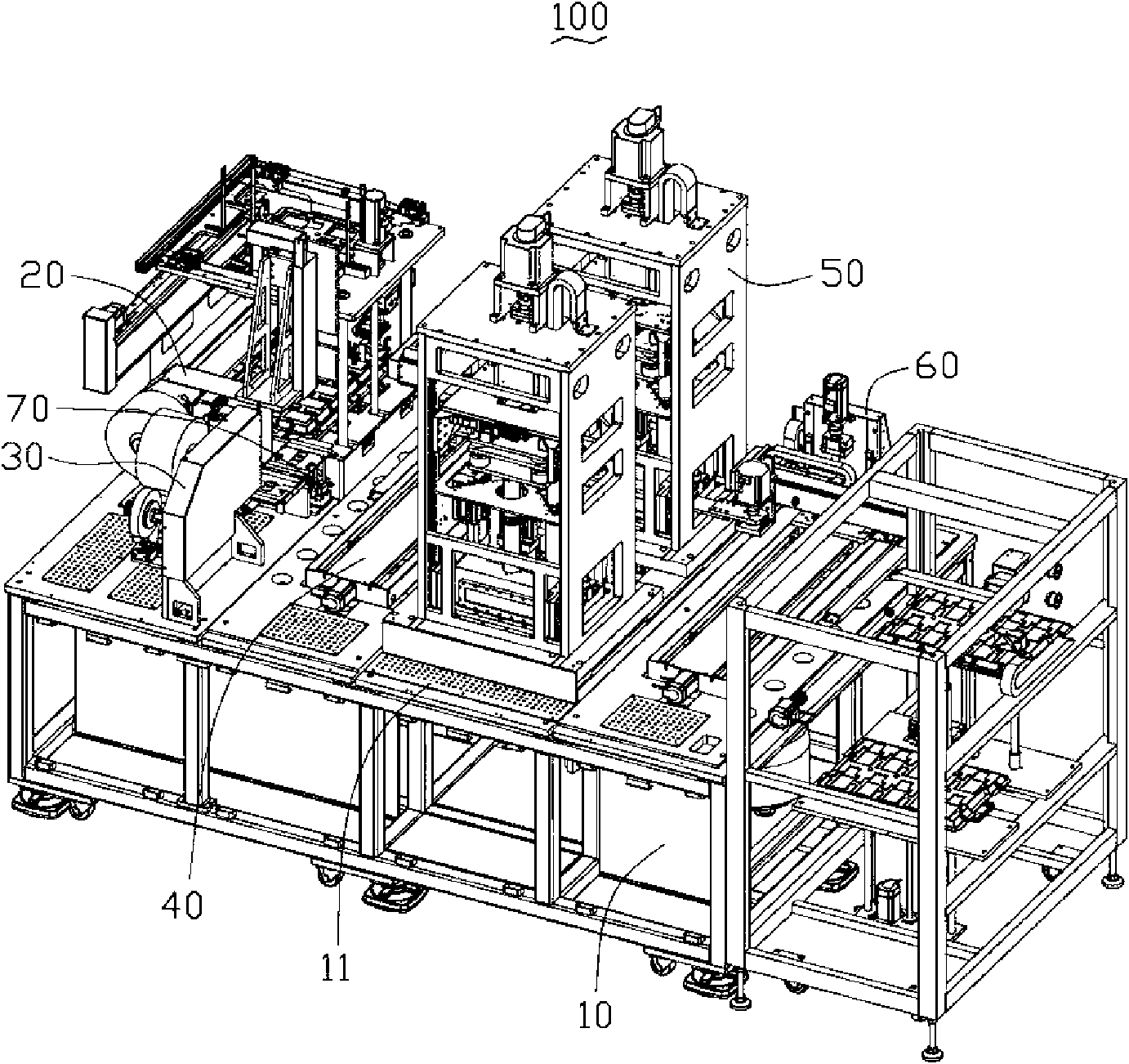
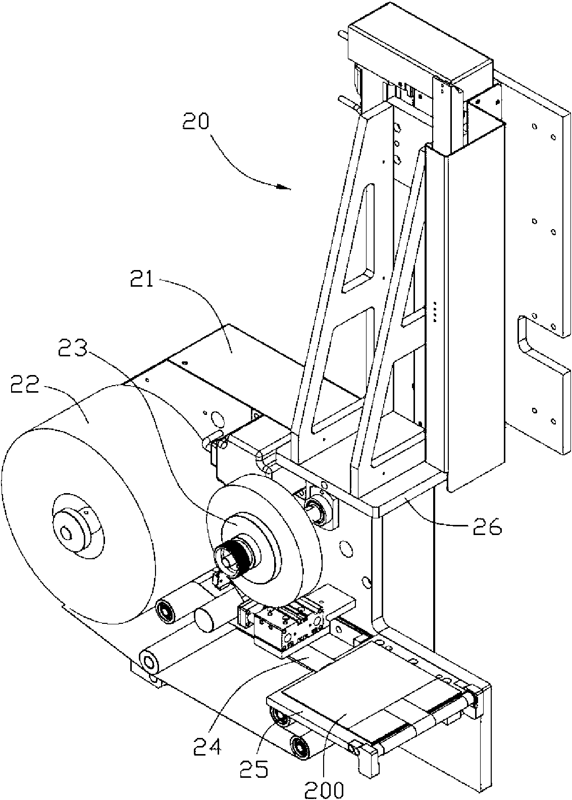
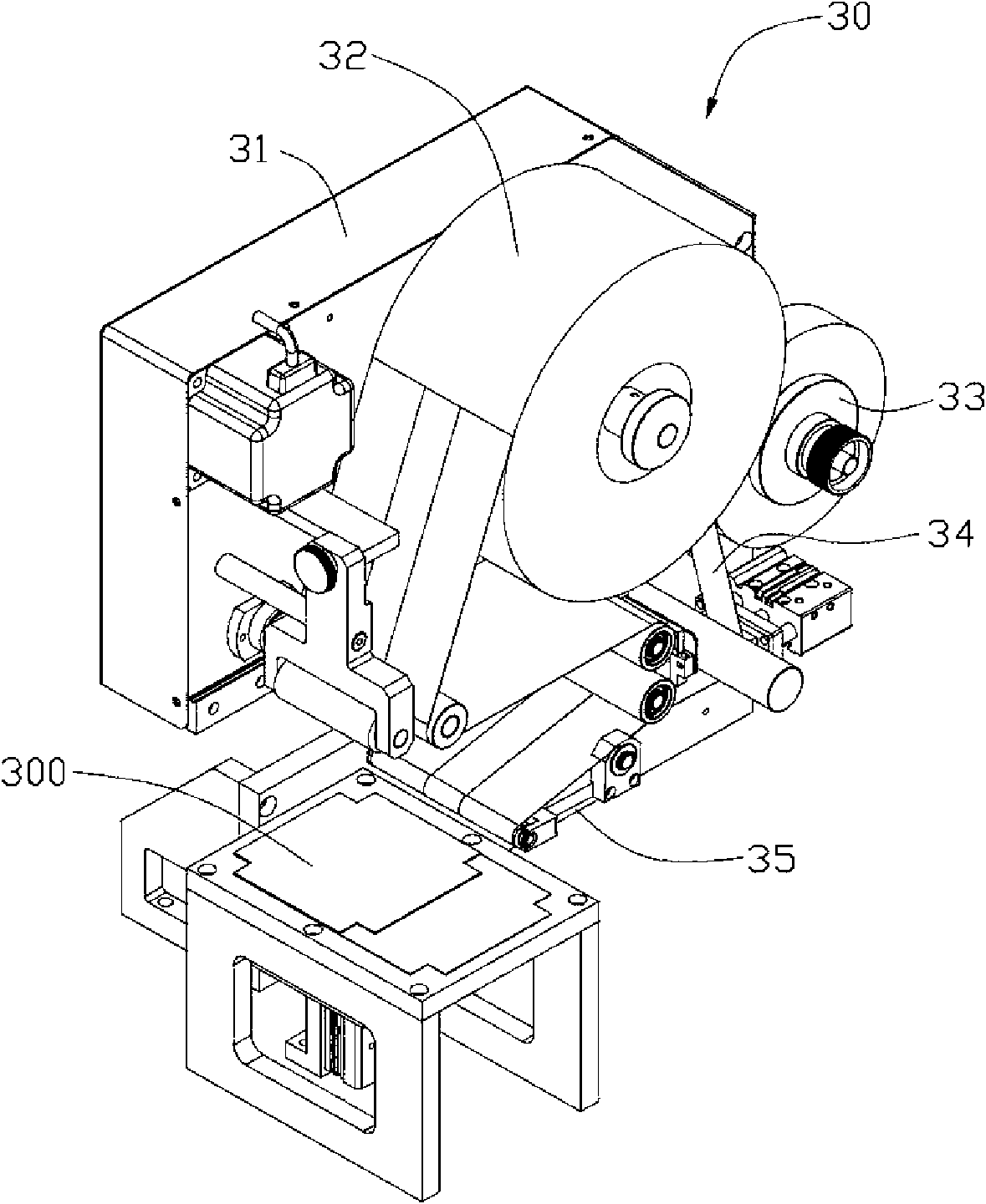
[0017] See figure 1 , The laminating device 100 provided by the embodiment of the present invention is used for the first substrate 200 (such as figure 2 Shown) and the second substrate 300 (as image 3 Shown) for bonding. The laminating equipment 100 includes a base 10, a first tearing device 20 fixed on the base 10, a second tearing device 30, a feeding mechanism 40, at least two vacuum laminating devices 50, an unloading mechanism 60, and positioning Agency 70. The feeding mechanism 40 and the unloading mechanism 60 are respectively located on opposite sides of the vacuum laminating device 50.

[0018] See also figure 2 with image 3 The first substrate 200 and the second substrate 300 may be glass plates used to manufacture touch panels and liquid crystal displays, or may be components used to manufacture devices such...


PUM


Abstract

The invention relates to bonding equipment, which is used for bonding a first substrate and a second substrate. The bonding equipment comprises a base, and a first dyestripping device, a second dyestripping device, vacuum bonding devices and a feeding mechanism which are arranged on the base, wherein the first dyestripping device and the second dyestripping device perform dyestripping on the first substrate and the second substrate respectively; at least two vacuum bonding devices are provided and are arranged on the base side by side; the feeding mechanism comprises a sliding rail arranged on the surface of the base and a loading platform movably arranged on the sliding rail; and after conveying the first substrate and the second substrate to one of the at least two vacuum bonding device, the loading platform slides on the sliding rail so as to convey the other first substrate and the other second substrate to the other vacuum bonding device. The bonding equipment has the advantages of high utilization rate and production efficiency.

Description

Technical field [0001] The present invention relates to a laminating equipment, in particular to a laminating equipment for manufacturing panels. Background technique [0002] In the process of manufacturing liquid crystal display panels or touch panels, two substrates are bonded in a vacuum bonding device. Under normal circumstances, after the substrate is processed, a protective film is attached to its surface to protect its appearance, and the protective film is removed by a film tearing device before lamination. [0003] A laminating equipment includes a film tearing device, a laminating mechanism and a conveyor belt connecting the two. First, the substrate to be bonded is put into the film tearing device for tearing the film, and then sent to the bonding mechanism through the conveyor belt for bonding. This type of laminating equipment eliminates the need for manual operation by arranging the film tearing device and the laminating mechanism into an assembly line, saving labo...

Claims


Application Information

Patent Timeline
Patent Type & Authority Applications(China)
IPC IPC(8): G02F1/13H05K13/04
CPCB32B17/10807H01L21/67011Y10T156/17
Inventor 林冬盛蔡子琦李建军
Owner JINCHENG FUTAIHUA PRECISION ELECTRONICS CO LTD
Learn More