Pilot frequency multiplexing determination method and device based on hybrid multiplexing

A pilot frequency multiplexing and determination method technology, applied in multi-frequency code systems, signal channels, etc., can solve the problems of DMRS design difficulties and difficult guarantees, and achieve the effects of saving control signaling, strong applicability, and avoiding damage

Inactive Publication Date: 2011-02-02
邳州诚德机械制造有限公司
View PDF3 Cites 15 Cited by
  • Summary
  • Abstract
  • Description
  • Claims
  • Application Information

AI Technical Summary

Problems solved by technology

Therefore, the design of DMRS caused great difficulties
In the CDM-based design method, since the form of the pilot frequency is exactly the same as the form of the PDSCH data, it is more convenient for the DMRS design to be compatible in different transmission modes. However, in the CDM mode, the channel coefficients on the resource carriers that require code division are basically unchanged. , in high-speed and large-delay scenarios, it is difficult to guarantee

Method used


Image

  • Pilot frequency multiplexing determination method and device based on hybrid multiplexing
  • Pilot frequency multiplexing determination method and device based on hybrid multiplexing
  • Pilot frequency multiplexing determination method and device based on hybrid multiplexing

Examples


Embodiment 1

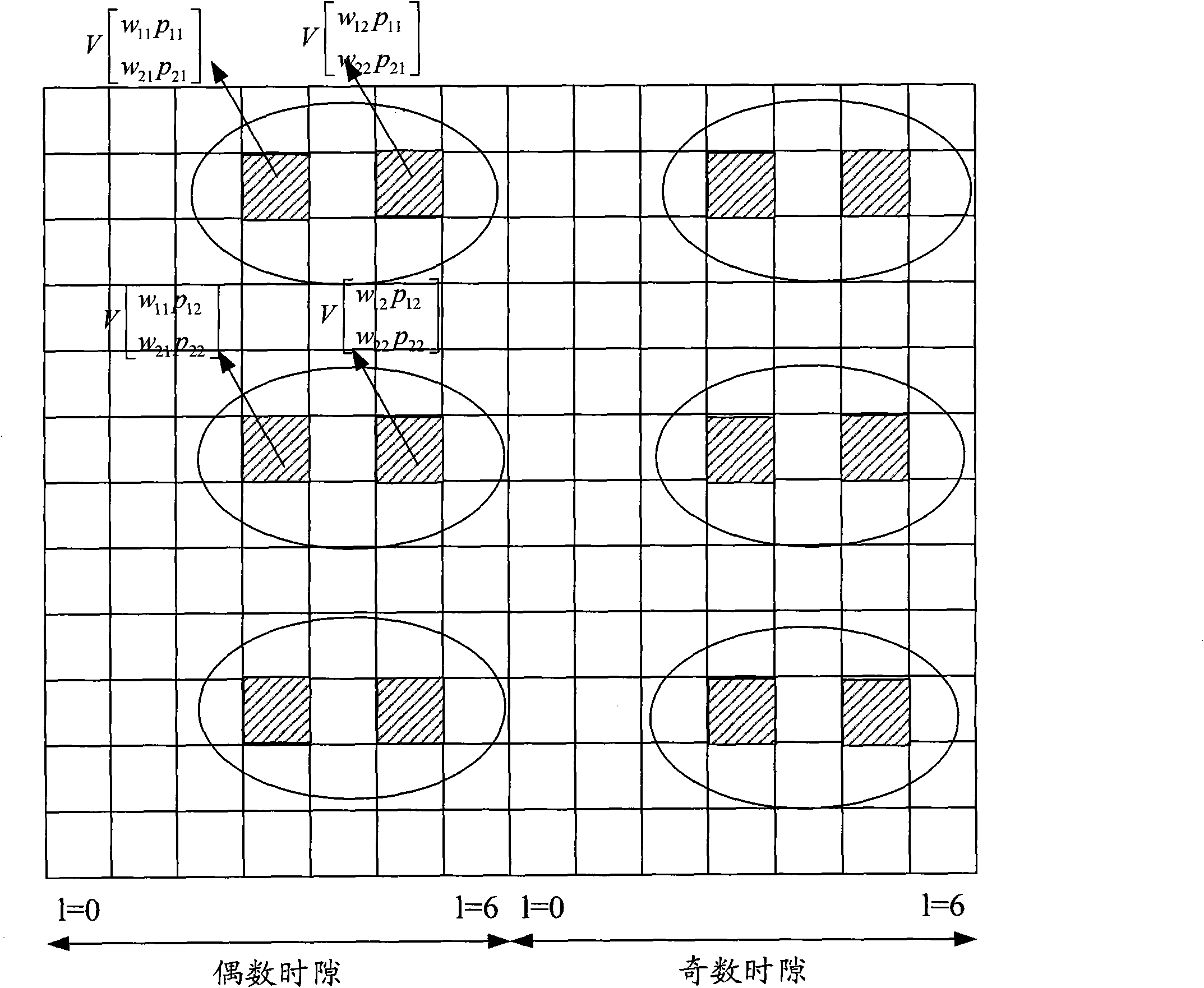
[0053] figure 1 It is a schematic diagram of the pilot bearing mode when the number of codeword streams and the number of layers is 2 in the present invention, as shown in figure 1 As shown, based on the DMRS pilot design idea described in the present invention, when the number of codeword streams is 2 and the number of layers is 2, a pilot pattern design is performed with different orthogonal codes between layer 1 and layer 2. Multiple access. Embodiment 1 is described based on a normal CP frame as an example. Let the orthogonal codeword used in codeword stream 1 be w 1 =[w 11 ,w 12 ], the orthogonal codeword for codeword stream 2 is w 2 =[w 21 ,w 22 ], p in the figure i,j Indicates the j-th pilot symbol corresponding to the i-th layer.

[0054] figure 1 The two resource elements (RE, Resource Element) in each ellipse in each ellipse respectively multiplex the pilots of the corresponding layers of stream 1 and stream 2, then the pilots of layer 1 and layer 2 are mul...

Embodiment 2

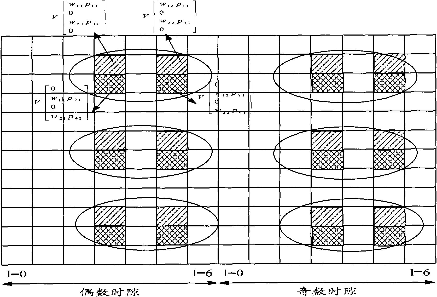
[0056] Figure 2A It is a schematic diagram of the pilot bearing mode when the number of codeword streams in the present invention is 2 and the number of layers is 3 or 4, such as Figure 2A As shown, based on the DMRS design idea described in the present invention, a pilot pattern design when the number of codeword streams is 2 and the number of layers is 4, in the figure, it is assumed that layer 1 and layer 2 correspond to the two codeword streams used by codeword stream 1 layers; layer 3 and layer 4 correspond to the two layers used by codeword stream 2. Then according to the design principle of the present invention, between layer 1 and layer 3, carry out multiplexing with different orthogonal codewords, between layer 2 and layer 4, carry out code division multiplexing with different orthogonal codes; Layer {1,3 } and layers {2, 4} are multiplexed by means of frequency division, that is, they are located on different frequency resource units. Also assume that the orthogo...

Embodiment 3

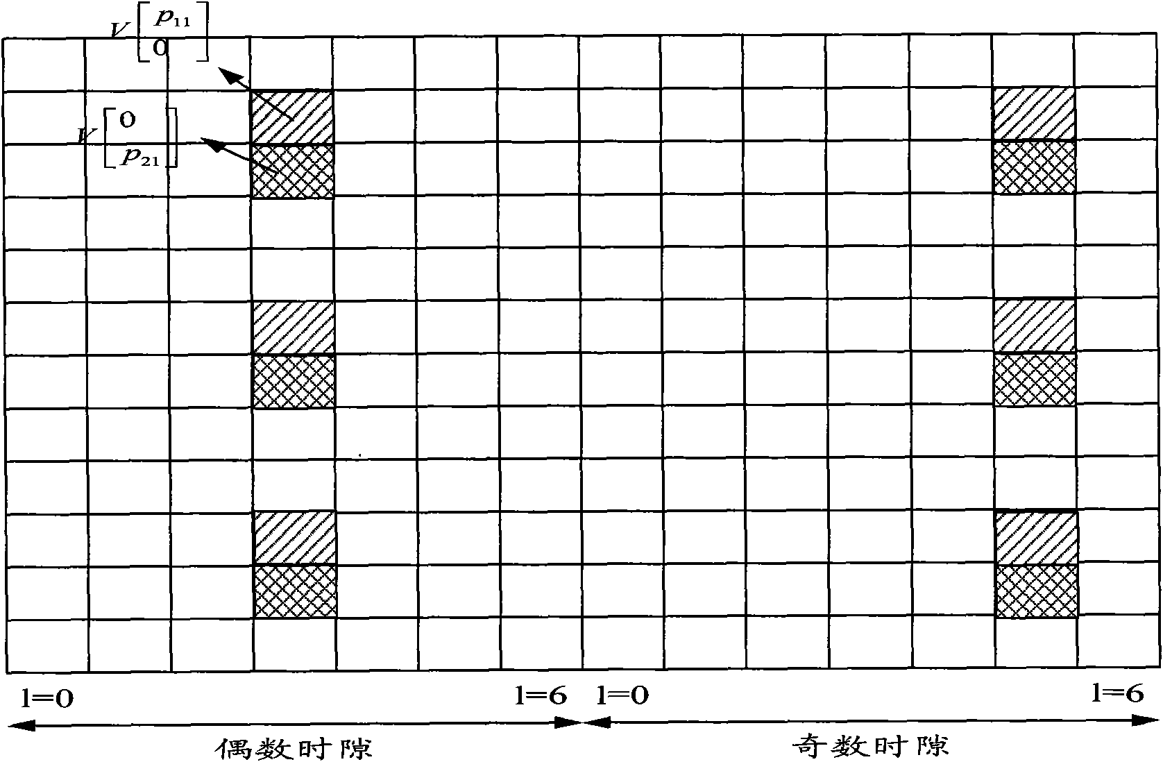
[0063] Figure 3A It is a schematic diagram of pilot bearing mode 1 when the number of codeword streams in the present invention is 2 and the number of layers is 5 or 6, Figure 3B It is a schematic diagram of pilot bearing mode 1 when the number of codeword streams in the present invention is 2 and the number of layers is 5 or 6, as shown in Figure 3A , 3B As shown, two types of layer numbers are given, namely 5 layers or 6 layers, and the number of codeword streams is 2, and the pattern mapping method based on the method provided by the present invention is given. It is assumed that the layers mapped to the codeword stream are {1, 2, 3}, and the layers mapped to the codeword stream 2 are {4, 5, 6}. Among them, code division multiplexing is performed between {1, 4}; {2, 5}; {3, 6}. Layers between the same codeword streams are frequency-division multiplexed.

[0064] When the number of layers is 5, the pilot signal corresponding to layer 6 is not multiplexed on the resour...


PUM


Abstract

The invention discloses a pilot frequency multiplexing mode determination method based on hybrid multiplexing, which comprises the following steps of: adopting the same pilot frequency multiplexing mode among layers corresponding to the same codeword stream, and adopting the same or different pilot frequency multiplexing modes among layers corresponding to different codeword streams; or grouping layers supported by the system, adopting the same pilot frequency multiplexing mode among layers in the same group, and adopting different pilot frequency multiplexing modes among layers in different groups. The invention also discloses a device for realizing the method, which comprises a layering unit and a multiplexing unit, wherein the layering unit is used for layering the same codeword stream or grouping the layers supported by the system; the multiplexing unit is used for adopting the same pilot frequency multiplexing mode among the layers corresponding to the same codeword stream and adopting the same or different pilot frequency multiplexing modes among the layers corresponding to different codeword streams, or adopting the same pilot frequency multiplexing mode among the layers in the same group, and adopting different pilot frequency multiplexing modes among the layers in different groups. The invention enables the applicability of UE (User Equipment) speed to be stronger.

Description

technical field [0001] The present invention relates to pilot frequency multiplexing technology, in particular to a method and device for determining a pilot frequency multiplexing mode based on hybrid multiplexing. Background technique [0002] The high-order multi-antenna technology is one of the key technologies of the Long Term Evolution Advanced (LTE-A or LTE-Advanced, Long Term Evolution Advanced) system, and is used to increase the system transmission rate. In order to achieve channel quality measurement and data demodulation after the introduction of high-order multi-antenna technology, the LTE-Advanced system defines two types of pilot symbols: data demodulation pilot (DMRS, Demodulation Reference Signal) and channel quality measurement pilot ( CSI-RS, Channel State Information-Reference Signal), wherein the demodulation pilot is used as a reference symbol for physical downlink shared channel (PDSCH, Physical Downlink Shared Channel) demodulation. Measurement pilot...

Claims


Application Information

Patent Timeline
Patent Type & Authority Applications(China)
IPC IPC(8): H04L27/26H04L5/02
Inventor 孙云锋姜静张峻峰朱常青
Owner 邳州诚德机械制造有限公司
Why Eureka
Try Eureka