
Linear track sliding device for flat knitting machine

A technology of flat knitting knitting machine and sliding device, which is applied in the directions of knitting, weft knitting, textile and paper making, etc., can solve the problems of inapplicability, affecting work efficiency, broken needles and defective products, etc., and achieves reasonable design structure, flexible and smooth sliding , the effect of long service life

Inactive Publication Date: 2011-02-09
郑文政
View PDF6 Cites 0 Cited by
  • Summary
  • Abstract
  • Description
  • Claims
  • Application Information

AI Technical Summary

Problems solved by technology

Its defect is: because the slider is supported on the track with a certain angle, under the action of the bearing, the slider can slide flexibly on the track, but the slider with a certain angle is connected with the machine head. During the sliding process, the gravity of the machine head is downward, causing the slider to contact the track, increasing the sliding resistance and causing metal friction, causing the track to wear, and gradually forming a sliding gap and inertia, so that the balance between the machine head and the needle row plate The relationship is affected, resulting in missing needles, broken needles and defective products in the knitting process, and seriously affecting work efficiency
But it is not suitable for the sliding of the machine head, it is only suitable for the movement of the carriage, and the sliding method and sliding structure are completely different

Method used


Image

  • Linear track sliding device for flat knitting machine
  • Linear track sliding device for flat knitting machine
  • Linear track sliding device for flat knitting machine

Examples


Embodiment Construction

[0024] The embodiments of the present invention will be described in detail below with reference to the accompanying drawings. This embodiment provides detailed implementation and specific operation procedures, but the protection scope of the present invention is not limited to the following embodiments.

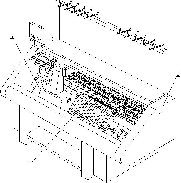
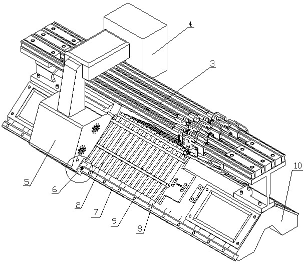
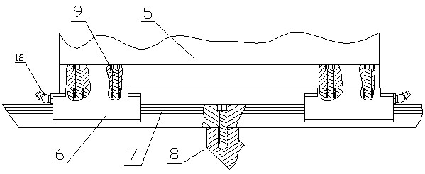
[0025] See Figure 1 ~ Figure 6 , The computerized flat knitting machine includes a frame 1, a needle row plate 2, a head slide 3, a case 4, a head 5, a fixing base 8 and a base 10. The fixing base 8 and the machine base 10 are integrated, the machine base 10 is fixed in the computerized flat knitting machine 1, the needle strip 2 and the head slide 3 are fixed on the machine base 10, and the chassis 4 is installed and fixed on the machine head 5. The head 5 is anastomosedly connected with the pin header 2. These structures are the same or equivalent to the prior art.

[0026] The present invention includes a slider 6, a rail 7, an annular ball 13, an arc surface 14, an annular...


PUM


Abstract

The invention relates to a linear track sliding device for a flat knitting machine, which is mainly applied to a full-automatic computer flat knitting machine. The device is characterized in that: the middle of the lower middle part of a sliding block has a T-shaped linear through groove structure, and a track is positioned in the through groove; the sliding block is provided with four annular grooves which are symmetrically distributed up and down, left and right, and a group of annular balls is arranged in each annular groove; the upper part of the track is provided with four arc surfaces, and the four arc surfaces are contacted with the four groups of annular balls; and the track is a linear track, the section of the track is transverse H-shaped, and the four arc surfaces are all positioned on the upper part of the transverse H-shape. The device is flexible and smooth to slide; the sliding block and the track are mutually tensioned, so the track is not damaged due to downward action of gravity of a machine head and the device has long service life; and the balls and the track have good lubricating performance.

Description

Technical field [0001] The invention relates to a rail sliding device, in particular to a linear rail sliding device for a flat knitting machine, which is mainly suitable for a fully automatic computerized flat knitting machine and belongs to the field of textile machinery. Background technique [0002] The fully automatic computerized flat knitting machine is an equipment dedicated to the processing of knitted garments, and its main application method is to knit yarn into garments. In the knitting process, the head of the flat knitting machine needs to slide back and forth repeatedly, and the sliding of the head needs to be realized by a slider supported on the rail. The structure of the slider and track system of the fully automatic computerized flat knitting machine in the prior art is as follows: the slider is equipped with a traditional bearing, the slider is clamped on the square track, and the bearing is connected to the square track. The rails are connected to achieve sl...

Claims


Application Information

Patent Timeline
Patent Type & Authority Applications(China)
IPC IPC(8): D04B15/00
Inventor 郑文政
Owner 郑文政
Learn More