
Road sweeper

A technology for road cleaning and vehicle body, applied in the field of sweepers, can solve the problems of high energy consumption, blockage of vacuum pipes and dust suction ports, high noise, etc., to achieve the effect of improving cleaning effect, improving cleaning efficiency and simple working process

Active Publication Date: 2011-02-09
ZHONGLULIAN TECH CO LTD
View PDF10 Cites 15 Cited by
  • Summary
  • Abstract
  • Description
  • Claims
  • Application Information

AI Technical Summary

Problems solved by technology

And there are following problems in existing road sweeper: 1, when existing road sweeper is in use, rubbish such as tree branch, bulk float, plastic bag often blocks up suction pipe and suction port, and is difficult to remove obstruction
Especially in spring, autumn and winter seasons with withered vegetation and sandstorms in the north, road sweepers are more likely to be blocked
2. During the cleaning process, the bristle brush of the road sweeper will easily adhere a large amount of dust to the bristle brush, which will cause the road surface to be cleaned to be untidy
3. The existing road sweeping vehicles still have many problems such as high manufacturing and use costs, high noise during use, and large exhaust emissions, which are not conducive to the large-scale promotion and use of road sweeping vehicles in cities
4. The energy consumption is too large, the use cost is too high, and it does not conform to the national energy conservation and emission reduction policy, especially in economically underdeveloped areas and cannot be promoted and used

Method used


Image

  • Road sweeper
  • Road sweeper
  • Road sweeper

Examples


Embodiment Construction

[0024] The present invention will be described in detail below in conjunction with the accompanying drawings and embodiments.

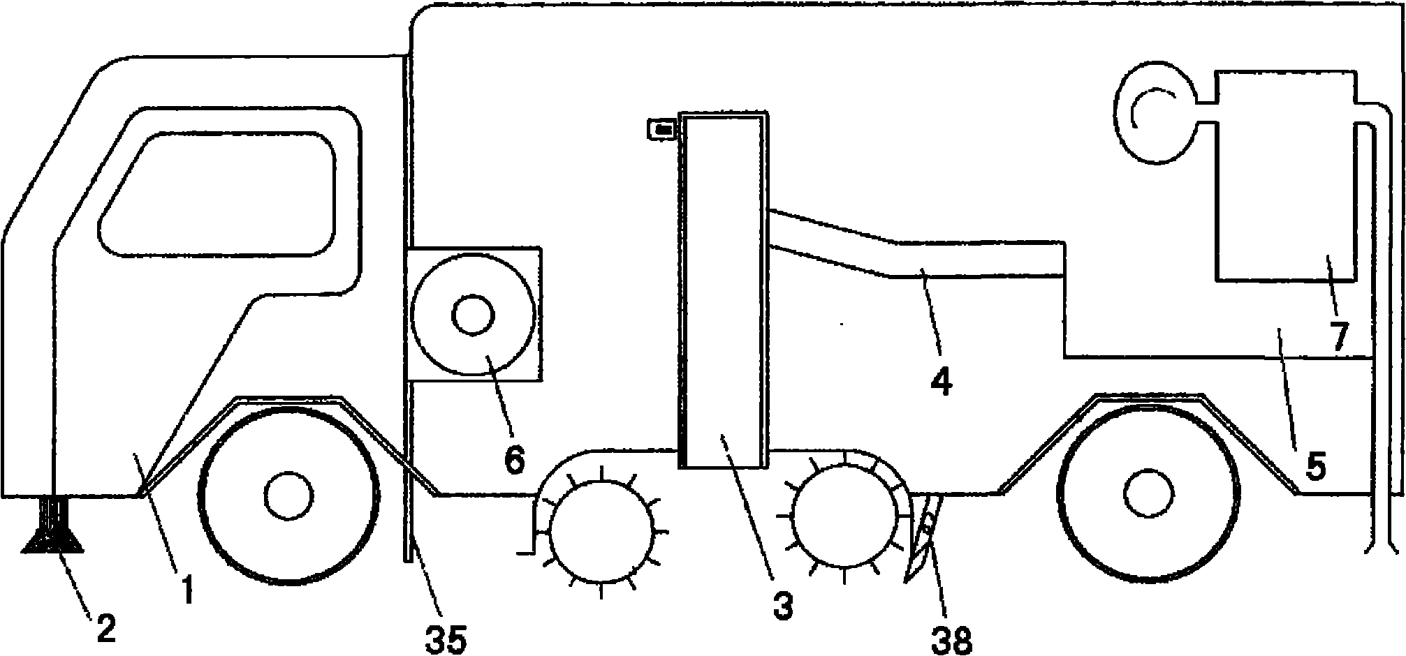
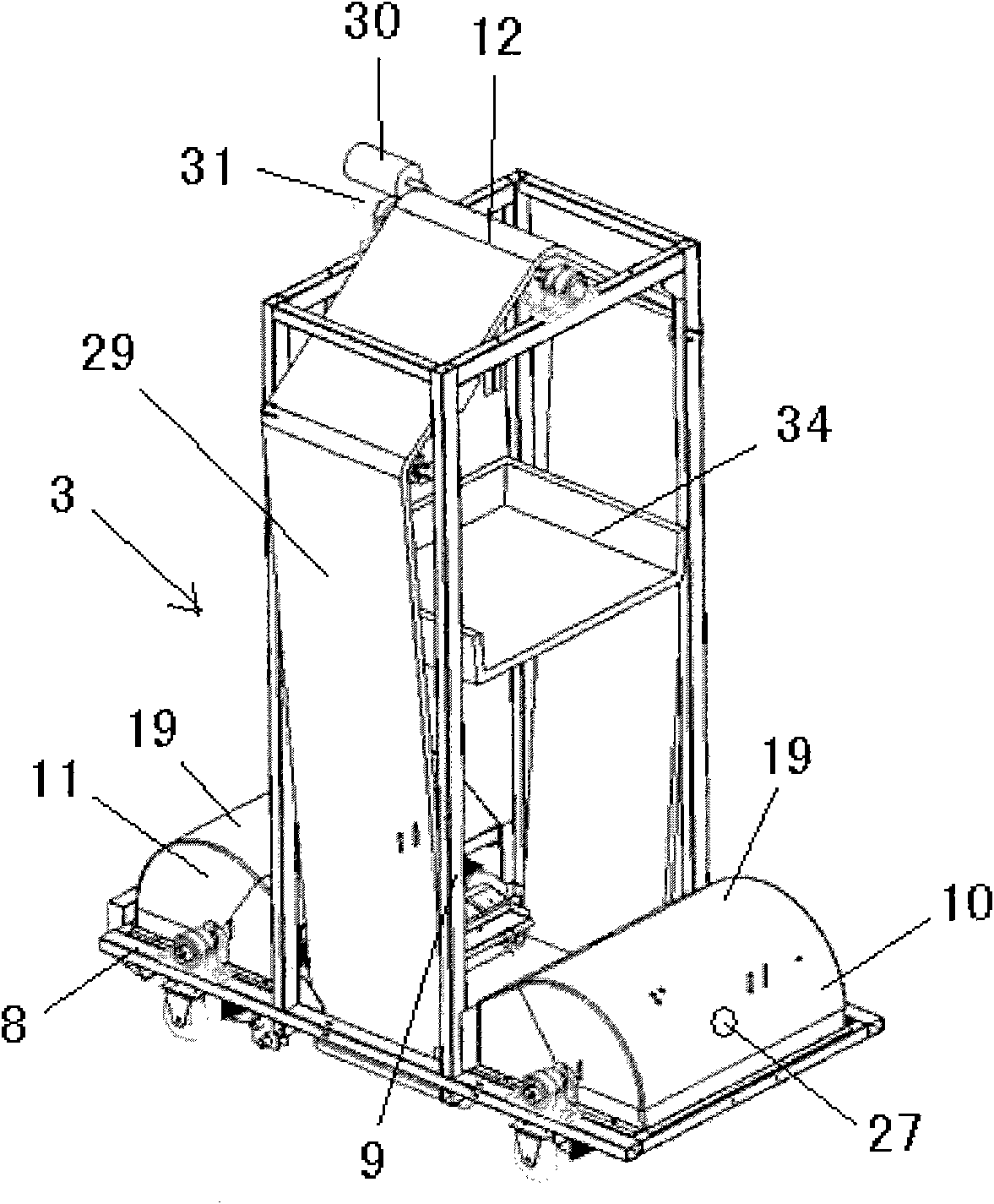
[0025] like figure 1 As shown, the present invention adopts mechanical simulation manual method to collect sundries and dust, and it comprises a car body 1 capable of walking. The two sides of the front part of the car body 1 are correspondingly provided with disc sweeping brushes 2 that expand the cleaning width. The internal control device controls its work. Between the front wheel and the rear wheel of the car body 1, a material collection and lifting device 3 with traveling small wheels is towed, and the material collecting and lifting device 3 will input the collected materials into a material collection box 5 through the material guide groove 4, Wherein, the material collection and lifting device 3 is powered by a power source 6 , and the power source 6 is arranged at the rear and lower part of the driver's cab of the car body 1 . At the after...


PUM


Abstract

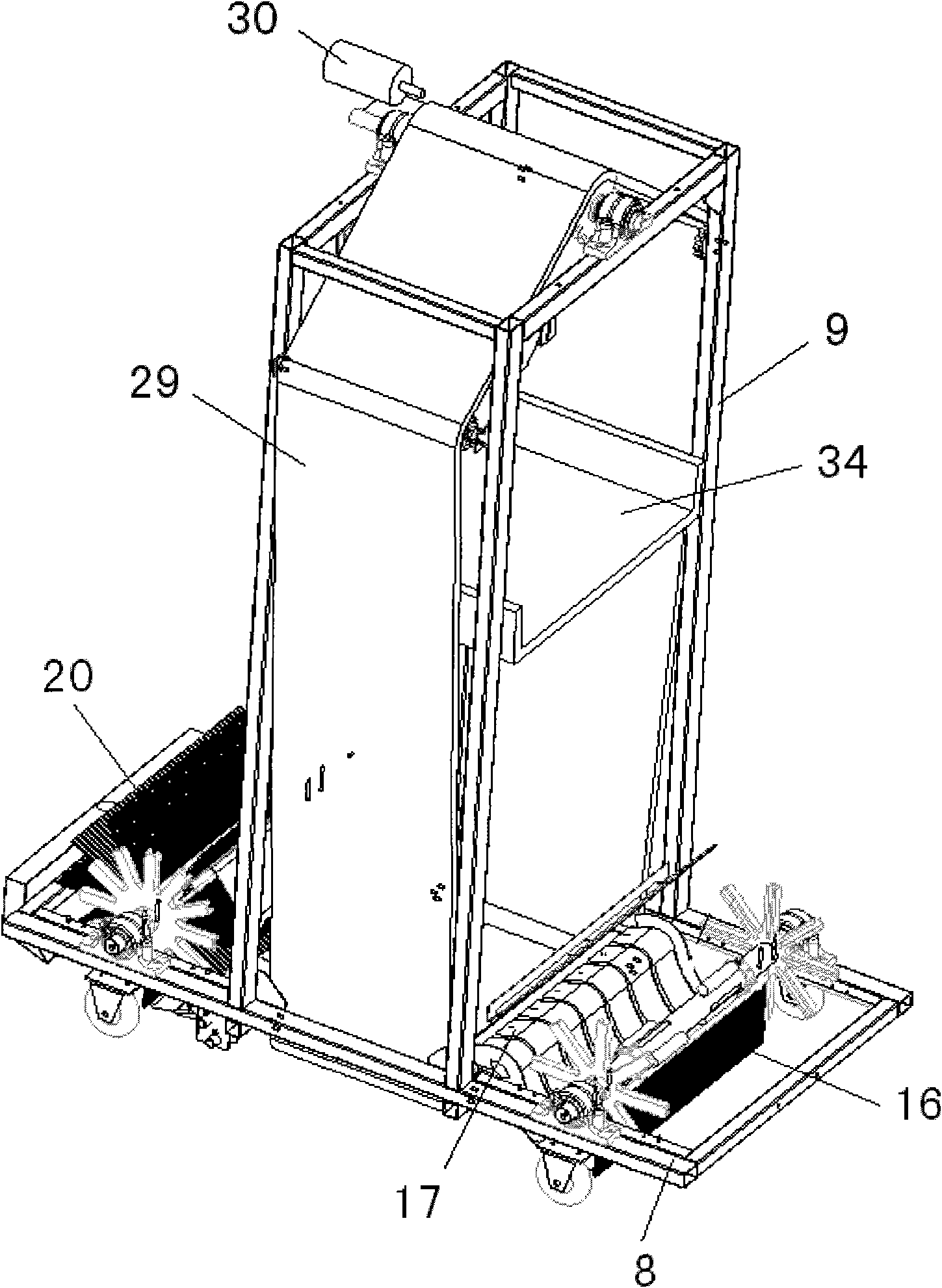
The invention relates to a road sweeper. The road sweeper comprises a vehicle body, wherein a disc brush sweeper and a material centralizer are correspondingly arranged on the two sides on the front part of the vehicle body; a material collecting and lifting device is hung between front wheels and rear wheels; the material collecting and lifting device inputs collected materials into a material collecting box through a material guide groove; the material collecting and lifting device is powered by a power supply in the vehicle body; the tail part of the vehicle body is provided with a dust adsorbing and removing device; the material collecting and lifting device comprises a horizontal bracket, a vertical bracket, a front rolling sweep group and a rear rolling sweep group; the vertical bracket is provided with a transport device; the transport device comprises an annular transport tape of which the middle part is provided with a C-shaped collecting and lifting groove and a drive shaft which is driven by a hydraulic motor for driving two drive wheels and driven wheels to rotate, so that the annular transport tape moves in the circumferential direction of the vertical direction; a collecting shovel is arranged inside the upper part of the vertical bracket; and when the materials in the C-shaped collecting and lifting groove move to the top along with the annular transport tape, the materials in the C-shaped collecting and lifting groove naturally fall into the collecting shovel and slide in the material collecting box in the vehicle body along the material guide groove. The road sweeper can be widely used for sweeping under various road conditions.

Description

technical field [0001] The invention relates to a sweeping vehicle, in particular to a road sweeping vehicle for cleaning various garbage in various environments. Background technique [0002] At present, most road sweepers use a high-power auxiliary engine installed on the chassis of the car to drive a high-pressure fan to generate negative pressure suction to achieve the purpose of cleaning the road. And there are following problems in existing road sweeper: 1, when existing road sweeper is in use, rubbish such as tree branch, bulk float, plastic bag often blocks up suction pipe and suction port, and is difficult to remove blockage. Especially in spring, autumn and winter seasons with withered vegetation and sandstorms in the north, road sweepers are more likely to be blocked. 2. During the cleaning process, the bristle brushes of the road sweeper can easily adhere a large amount of dust to the bristle brushes, which will cause the road surface to be cleaned to be untidy...

Claims


Application Information

Patent Timeline
IPC IPC(8): E01H1/08
Inventor 张国军
Owner ZHONGLULIAN TECH CO LTD
Learn More