
System for detecting software bug triggered during practical running of computer program

A computer program and actual operation technology, applied in the field of detection systems that trigger software vulnerabilities, can solve problems such as failure to detect vulnerabilities, inability to directly analyze binary code, large time and system resource overhead, etc., to improve software vulnerabilities and vulnerabilities Possibility, high program executable path coverage, and the effect of reducing resource and time overhead

Inactive Publication Date: 2011-02-09
SHANGHAI JIAO TONG UNIV
View PDF2 Cites 40 Cited by
  • Summary
  • Abstract
  • Description
  • Claims
  • Application Information

AI Technical Summary

Problems solved by technology

[0004] However, both dynamic program analysis and static program analysis have their insurmountable shortcomings
For dynamic program analysis technology, because the program can only be executed along one path during each dynamic execution, in order to achieve satisfactory path coverage, we must repeat the dynamic analysis for a sufficient number of times, but even so It is also difficult to achieve 100% path coverage
For static program analysis technology, although it can achieve 100% program path coverage, it cannot detect those vulnerabilities that are triggered when the program is actually running, and the false alarm rate of general vulnerabilities is high. Static analysis of an entire large program can incur significant time and system resource overhead
More importantly, existing related systems often require program source code to perform program analysis and vulnerability detection, and cannot directly analyze the binary code of the target program. This shortcoming also limits the use of these systems

Method used


Image

  • System for detecting software bug triggered during practical running of computer program
  • System for detecting software bug triggered during practical running of computer program
  • System for detecting software bug triggered during practical running of computer program

Examples


Embodiment Construction

[0019] The embodiments of the present invention will be described in detail below in conjunction with the accompanying drawings. This embodiment is implemented on the premise of the technical solution of the present invention, and detailed implementation methods and specific operating procedures are provided, but the scope of protection of the present invention is not limited to the following the described embodiment.

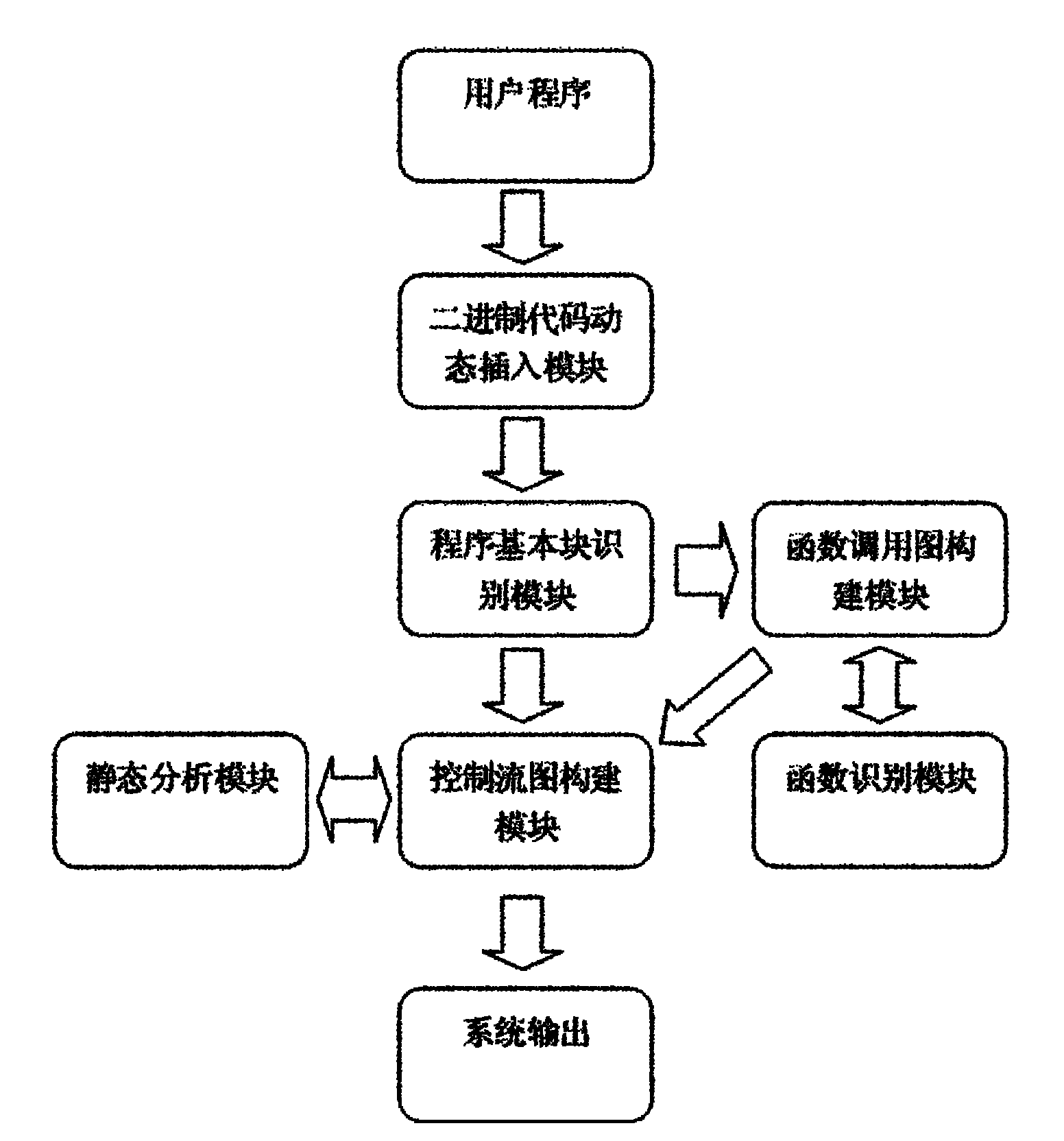
[0020] like figure 1As shown, this embodiment includes: a binary code dynamic insertion module, a program basic block identification module, a function call graph construction module, a control flow graph construction module, a function identification module, and a static analysis module. The binary code dynamic insertion module can insert user-defined analysis code into any position of the program, track the system API called by the program, and finally return the analysis result through the callback function provided by the custom program analysis file and pa...


PUM


Abstract

The invention relates to a system for detecting a software bug triggered during practical running of a computer program in the technical field of computers. The system comprises a binary code dynamic inserting module, a program basic block recognizing module, a function call graph constructing module, a control flow graph constructing module, a function recognizing module and a static analysis module. By combining two technologies of dynamic program analysis and static analysis path complementation, the invention not only can detect the bugs which can be triggered during the practical running of the program but also can reach higher program path coverage rate, carry out bug detects on the path which is not covered in the dynamic analysis process, improve the success rate of bug detection and reduce the false rate of the bugs. Meanwhile, the static analysis path complementation technology only analyzes a path which is not executed in dynamic analysis instead of all program paths, thereby greatly reducing the cost on time and system resources.

Description

technical field [0001] The invention relates to a detection system in the field of computer technology, in particular to a detection system for triggering software loopholes when a computer program actually runs. Background technique [0002] Program analysis technology refers to the analysis technology that deduces its structure and data flow for computer programs. In the process of software maintenance detection and software understanding, we need to analyze the structure and data flow of the target program, and the output of the program analysis system is generally a data flow graph and a control flow graph. The data flow graph expresses the transformation and transfer process of information in the program system in a graphical way, especially the situation where data is referenced and defined; the control flow graph often uses the form of a graph or an abstract syntax tree to describe the program structure. [0003] Dynamic program analysis technology is a technology th...

Claims


Application Information

Patent Timeline
IPC IPC(8): G06F11/36
Inventor 张若愚王卓周侃黄实秋黄山
Owner SHANGHAI JIAO TONG UNIV
Learn More