
High-power travelling wave tube amplifier for broadband

A traveling wave tube amplifier and traveling wave tube technology are applied to amplifiers with propagation time effect and other directions, which can solve the problem of small dynamic range of amplifiers and achieve the effect of improving the dynamic range.

Inactive Publication Date: 2011-02-09
中国船舶重工集团公司第七二三研究所
View PDF6 Cites 5 Cited by
  • Summary
  • Abstract
  • Description
  • Claims
  • Application Information

AI Technical Summary

Problems solved by technology

The magnification factor G1 of the FET usually does not change. However, the power characteristic curve of the TWT is not linear in the whole range. When the input power of the TWT exceeds a certain range, the linear relationship between the input power and the output power is lost.
It can be seen that if the figure 1 The amplifier structure shown, the dynamic range of the overall amplifier is small

Method used


Image

  • High-power travelling wave tube amplifier for broadband
  • High-power travelling wave tube amplifier for broadband
  • High-power travelling wave tube amplifier for broadband

Examples


Embodiment Construction

[0024] The present invention will be described in detail below with reference to the accompanying drawings and examples.

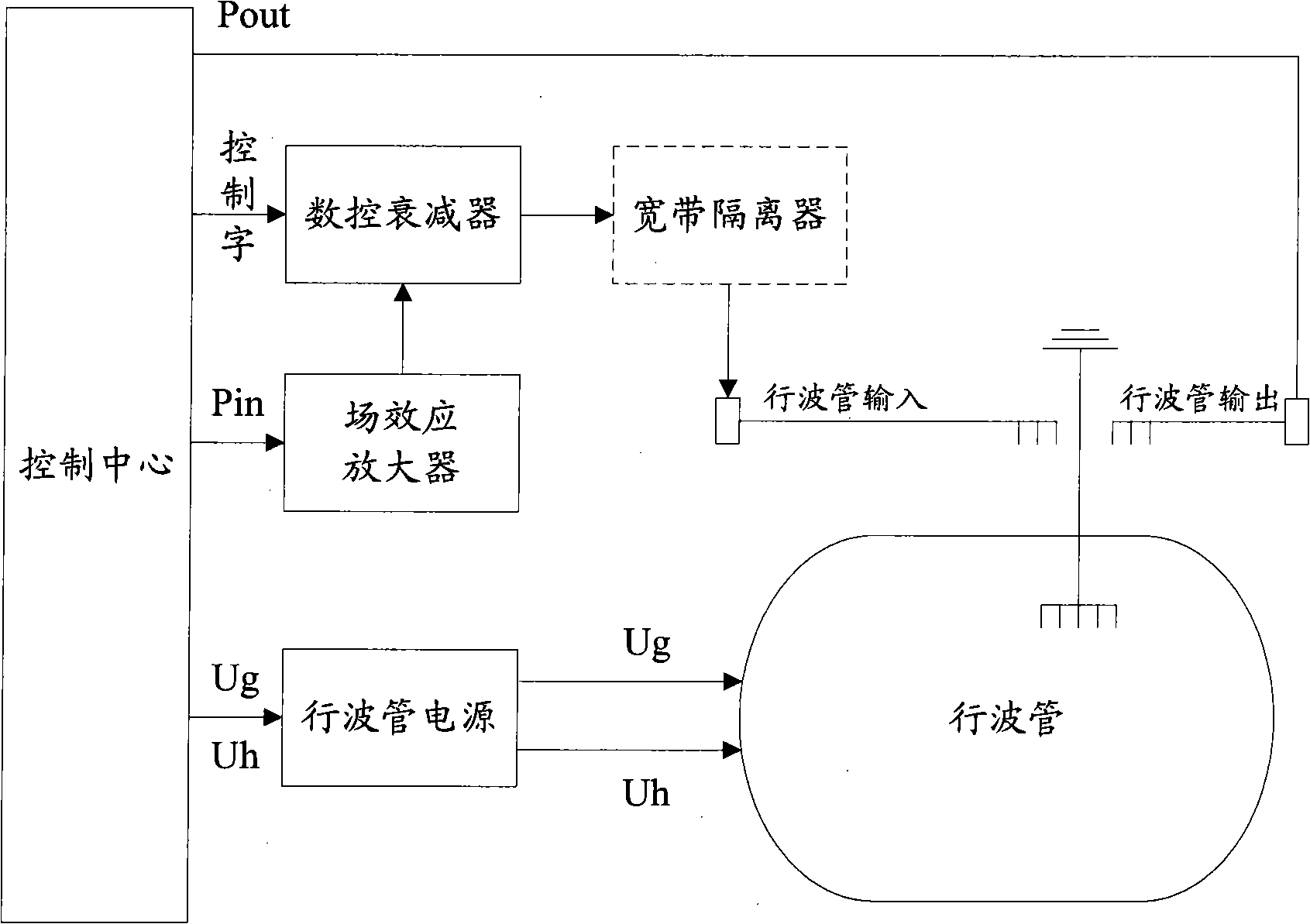
[0025] The invention provides a broadband high-power traveling wave tube amplifier. The traveling wave tube amplifier adds a numerically controlled attenuator between the FET and TWT of the conventional GFET-TWT, and uses a computer to input control codes to the numerically controlled attenuator to realize the attenuation multiple. , so as to control the signal power input to the TWT, so as to control the input power of the TWT within the range of the linear region.

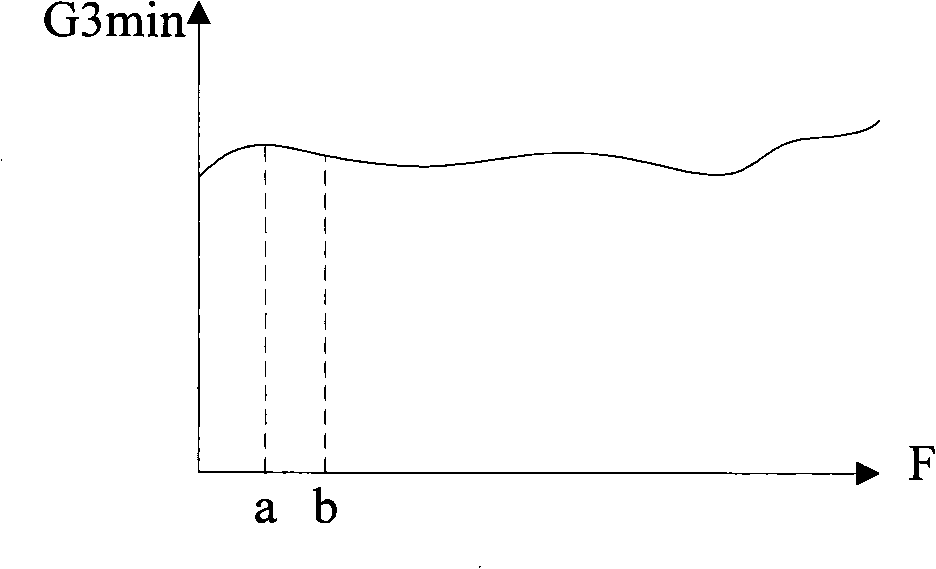
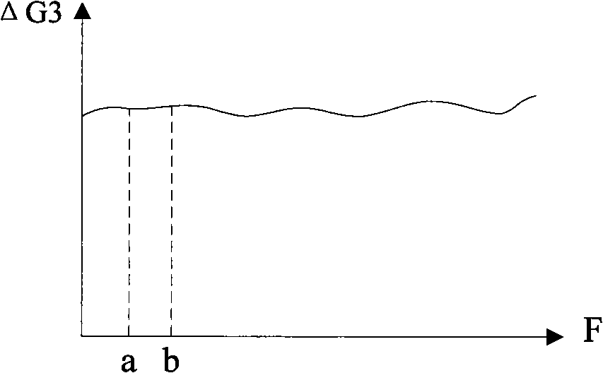
[0026] In addition, according to the working principle of the traveling wave tube, in order to ensure the saturated output power of the traveling wave tube at the low end and high end of the frequency, the synchronous voltage (Uh) required by it is different. In order to better control the high-frequency gain of the traveling wave tube, the present invention finds out the optimal synchronous ...


PUM


Abstract

The invention discloses a high-power travelling wave tube amplifier for broadband, which comprises a field effect amplifier, a numerical control attenuator, a travelling wave tube, a power supply of the travelling wave tube and a control center, wherein the control center is provided with a plurality of travelling wave tube parameters Ug and Uh. The following experiments are carried out aiming at each frequency point: each group of travelling wave tube parameters is arranged in the travelling wave tube sequentially through the power supply of the travelling wave tube; when the travelling wave tube works in each group of the travelling wave tube parameters, the control center adjusts the attenuation times G3 of the numerical control attenuator, collects the output power of the travelling wave tube and changes according to whether the output power changes along with the attenuation times G3 or not so as to obtain the dynamic range of the travelling wave tube. The parameters of the travelling wave tube and the attenuation times are selected when the maximum dynamic range appears and form a relation list aiming at each frequency point. In the course of actual amplification work, the corresponding Ug, Uh and G3 are searched in the relation list according to the frequency of an input signal so that the linear amplification of the integral amplifier in a larger range can be realized.

Description

technical field [0001] The invention relates to the technical field of high-power signal simulators, in particular to a broadband high-power traveling wave tube amplifier. Background technique [0002] The existing field effect traveling wave tube amplification chain amplifier (GFET-TWT) includes a field effect amplifier (FET) and a traveling wave tube (TWT), and the input signal Pin is amplified and output Pout through the FET and the TWT respectively. [0003] The amplification factor of the existing chain amplifier is the sum of the amplification factors G1 and G2 of the FET and the TWT. The magnification factor G1 of the FET usually does not change. However, the power characteristic curve of the TWT is not linear in the entire range. When the input power of the TWT exceeds a certain range, the linear relationship between the input power and the output power is lost. It can be seen that if the figure 1 With the amplifier structure shown, the dynamic range of the overall...

Claims


Application Information

Patent Timeline
IPC IPC(8): H03F3/58
Inventor 蒋洪卫沙亮张彦
Owner 中国船舶重工集团公司第七二三研究所
Learn More