Refrigerator
A technology for a refrigerator and a storage room, applied in the field of refrigerators, can solve the problems of the quality degradation of the refrigerator, the damage of the infrared sensor 309, the failure of the detection function to work, etc., so as to achieve the effects of improving the detection accuracy and suppressing the temperature change.
- Summary
- Abstract
- Description
- Claims
- Application Information
AI Technical Summary
Problems solved by technology
Method used
Image
Examples
Embodiment approach 1
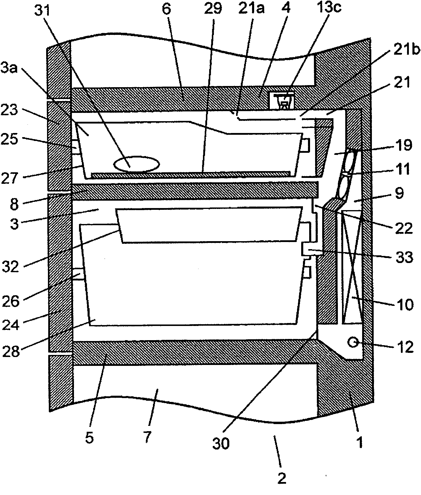
[0105] figure 1 It is a side sectional view of the main part of the refrigerator in the first embodiment of the present invention, Figure 2A It is a side sectional view of the infrared sensor mounting part of the refrigerator, Figure 2B Yes Figure 2A Enlarged view of the main parts of.
[0106] in figure 1 , Figure 2A Among them, the freezer compartment 3, which is a part of the storage room of the refrigerator main body 2 constituted by the heat-insulated box 1, is divided into refrigerated refrigerators with different temperature zones by the upper upper heat-insulating partition 4 and the lower lower heat-insulating partition 5 Room 6 and Vegetable Room 7. In addition, the opening portion (not shown in the figure) of the freezing compartment 3 is provided with divided bodies 8 connecting the left and right ends of the opening portion.
[0107] In this embodiment, the split body 8 connects only the left and right ends of the opening. However, when the freezer compartment 3 ...
Embodiment approach 2
[0176] Hereinafter, embodiments of the present invention will be described in detail using the drawings.
[0177] In the second embodiment, detailed descriptions of the same parts as the structure and technical idea described in the first embodiment will be omitted, and the structure that can apply the same technical idea as the content described in the first embodiment can be A structure formed by combining the technical contents and structures described in Embodiment 1 is realized.
[0178] Figure 4 It is a side cross-sectional view of the main part of the refrigerator in Embodiment 2 of this invention.
[0179] In general, the infrared sensor 13 equipped in the freezer compartment 3, which is a storage room in the refrigerator, is composed of an infrared element part 43, which detects the amount of infrared rays emitted from objects in the field of view, and then converts it The infrared light receiving part 40 that becomes an electric signal; the thermistor 42 that measures the...
Embodiment approach 3
[0189] Hereinafter, embodiments of the present invention will be described in detail using the drawings.
[0190] In the third embodiment, for the same parts as the structure and technical idea described in the first and second embodiments, detailed descriptions thereof are omitted, and the contents described in the first and second embodiments can be applied. The structure of the same technical idea can realize the structure formed by combining the technical content and structure described in the first embodiment.
[0191] Figure 5A It is a side sectional view of the main part of the refrigerator in Embodiment 3 of this invention. Figure 5B It is a bird's-eye plan view of the freezer compartment of the refrigerator in Embodiment 3 of this invention.
[0192] In general, the infrared sensor 13 equipped in the freezer compartment 3, which is a storage room in the refrigerator, is composed of an infrared element part 43, which detects the amount of infrared rays emitted from objects ...
PUM
 Abstract
Description
Claims
Application Information
 - R&D
- Intellectual Property
- Life Sciences
- Materials
- Tech Scout
- Unparalleled Data Quality
- Higher Quality Content
- 60% Fewer Hallucinations
Browse by: Latest US Patents, China's latest patents, Technical Efficacy Thesaurus, Application Domain, Technology Topic, Popular Technical Reports.
© 2025 PatSnap. All rights reserved.Legal|Privacy policy|Modern Slavery Act Transparency Statement|Sitemap|About US| Contact US: help@patsnap.com


