
Optical pickup apparatus

a pickup apparatus and optical technology, applied in the field of optical pickup apparatus, can solve the problems of complex configuration enlargement of the size, and insufficient value of the product of the optical pickup apparatus, so as to suppress the deviation of the temperature on the optical surface, and reduce the risk of entanglemen

Pending Publication Date: 2007-03-08
KONICA MINOLTA OPTO
View PDF10 Cites 4 Cited by
  • Summary
  • Abstract
  • Description
  • Claims
  • Application Information

AI Technical Summary

Benefits of technology

[0013] As a result of a keen examination of the problems from another viewpoint by the inventors of the present application, we have found that it is possible to perform information recording and / or information reproducing suitably to an optical information recording medium, for example, by skew adjustment, which tilts each of the objective optical elements to the optical axis thereof, when the changes of a coma aberration and an stigmatism are severally suppressed to be within a fixed range (i.e. ±0.02 λ1 rms or less, or ±0.02 λ2 rms or less) during a period of a change of the temperature distribution of the optical surface of each of the objective optical elements before used, to the temperature distribution when used. Here, there are a method of using an objective optical element capable of suppressing aberration changes even if a temperature distribution arises, a method of suppressing the deviation of a temperature distribution arising in the direction perpendicular to the optical axis in the inside of an objective optical element, and the like as the methods of suppressing the deterioration of the spherical aberration, the coma aberration and the astigmatism to be within a range of ±0.02 λ1 rms or less, or ±0.02 λ2 rms or less.
[0017] In the optical pickup apparatus of the second embodiment, the heat conduction ratios of the internal holding member and the external holding member differ from each other in the lens holder. For example, when the heat conduction ratio of the external holding member is lower, the heat from a heat source is shielded by the heat shield function of the external holding member. Consequently, the quantity of the heat transmitted to the internal holding member touching the objective optical elements directly decreases, and the heat diffuses in the external holding member to be uniformly transmitted to the internal holding member. Because the transmitted heat is radiated in the internal holding member and is diffused to be transmitted in the external holding member, the heat is uniformly transmitted to the objective optical elements. By such a configuration, the deviation and the highest temperature of a temperature distribution generated on the optical surface of each of the objective optical elements can be suppressed, and the change of the aberration caused by a temperature change can be suppressed as a result. Moreover, when the heat conduction ratio of the internal holding member is lower, the heat from the heat source is radiated in the external holding member. Furthermore, by the heat shield function of the internal holding member, the heat transmission to each of the objective optical elements is suppressed, and by the diffusion of the heat transmitted into the internal holding member to be uniformly transmitted to each of the objective optical elements, the deviation and the highest temperature of a temperature distribution generated in the optical surface thereof can be suppressed. As a result, the changes of the aberration caused by the temperature changes can be suppressed.
[0021] Because in the optical pickup apparatus of the third embodiment, the lens holder is equipped with the radiating fin, the heat radiation is performed before the heat from a heat source has been transmitted to each of the objective optical elements, and consequently the heat quantity transmitted to each of the objective optical elements is decreased. Thereby, the deviation and the highest temperature of a temperature distribution generated on the optical surface of each of the objective optical elements can be suppressed, and the changes of the aberration caused by the temperature changes can be suppressed as a result.
[0024] Further, in the optical pickup apparatus of the fourth embodiment, the lens holder has a radiating means for reducing heat transfer from an external heat source to the first and second objective optical element through the lens holder.
[0029] In the optical pickup apparatus of the fifth embodiment, the inorganic particles having the average diameter of 30 nm or less are dispersed in the plastic lens. The refractive index changes of the inorganic particles, caused by a temperature change are generally smaller than those of resins. Accordingly, by using the objective optical elements each made of a plastic material which is a resin in which inorganic particles having an average diameter of 30 nm or less are dispersed, the refractive index changes can be suppressed with the transparency thereof being secured. As a result, the changes of the aberration caused by the temperature changes can be suppressed. Moreover, by raising the heat conduction ratio of each of the objective optical elements by dispersing the inorganic particles, the heat transmitted to each of the objective optical elements is diffused. Thereby, the deviation of the temperature on the optical surface can be suppressed, and the changes of the aberration caused by the temperature changes can be suppressed.

Problems solved by technology

Now, only the possibility of information recording and / or information reproducing suitable to such a high density DVD is not enough to have a sufficient value as a product of an optical pickup apparatus.
However, because the objective lens is required to have an extremely high aberration characteristic in information recording and / or information reproducing to a high density DVD owing to changes of the light source wavelengths to be shorter ones and adoption of a high NA, it is sometimes difficult to suitably perform the information recording and / or the information reproducing to a DVD and a CD using the same object lens.
When actuators are separately provided to them to drive them independently, increase of the number of the actuators causes complexity of the configuration of the optical pickup apparatus and enlargement of the size thereof.
Furthermore, there is also a situation in which it is unnecessary to drive the objective optical elements independently because, while one of the objective optical elements is used, the other objective optical element is not used.
Because the conducting quantity becomes larger for acquiring the larger driving force, a heat value also becomes larger, and the existence of a problem in which the objective optical elements are heated by the generated heat which has been transmitted through the supporting member becomes clear.
Moreover, the existence of another problem in which a deviation arises in the temperature distribution on the optical surfaces of the objective optical elements based on the relation between the arrangement of the actuator and the arrangement of the two objective optical elements also becomes clear.
When a temperature difference becomes excessive in the temperature distributions in the direction perpendicular to the optical axis in each of the objective optical elements and / or the optical axis direction thereof, it is apprehended that thermal expansions of the optical surfaces are caused and aberration deterioration impeding the suitable information recording and / or the suitable information reproducing is caused.
However, for example, in the optical pickup apparatus installed in a notebook-size personal computer and the like, it is difficult to separately provide the bulky temperature adjustment means owing to the restriction of a space or the like.
However, the temperature distribution at the transient time of becoming a steady state from a power activation is not fixed, and the temperature distribution changes every moment.
As a result, it is difficult to acquire an optical surface shape generating an always good aberration to the temperature distribution changing variously like this.

Method used


Image

  • Optical pickup apparatus
  • Optical pickup apparatus
  • Optical pickup apparatus

Examples


Embodiment Construction

[0039] In the present invention, the description “a variation of each of a coma aberration and an astigmatism is not more than 0.02 λrms” means that the maximum value of the variations of a coma aberration and an astigmatism is 0.02 λrms or less when recording and / or reproducing are preformed by using a light source emitting a light flux of a wavelength λ by an optical pickup apparatus in comparison with the coma aberration and the astigmatism at the time of not driving the optical apparatus.

[0040] In the optical pickup apparatus mentioned above, it is preferable that the supporting member is driven by an actuator at the time of performing information recording and / or information reproducing to either of the first and the second information recording media. The more simplification of the optical pickup apparatus can be achieved by such a configuration in comparison with the case where the objective optical elements are severally driven by actuators. On the other hand, because the l...


PUM

PropertyMeasurementUnit
diameteraaaaaaaaaa
diameteraaaaaaaaaa
diameteraaaaaaaaaa

Abstract

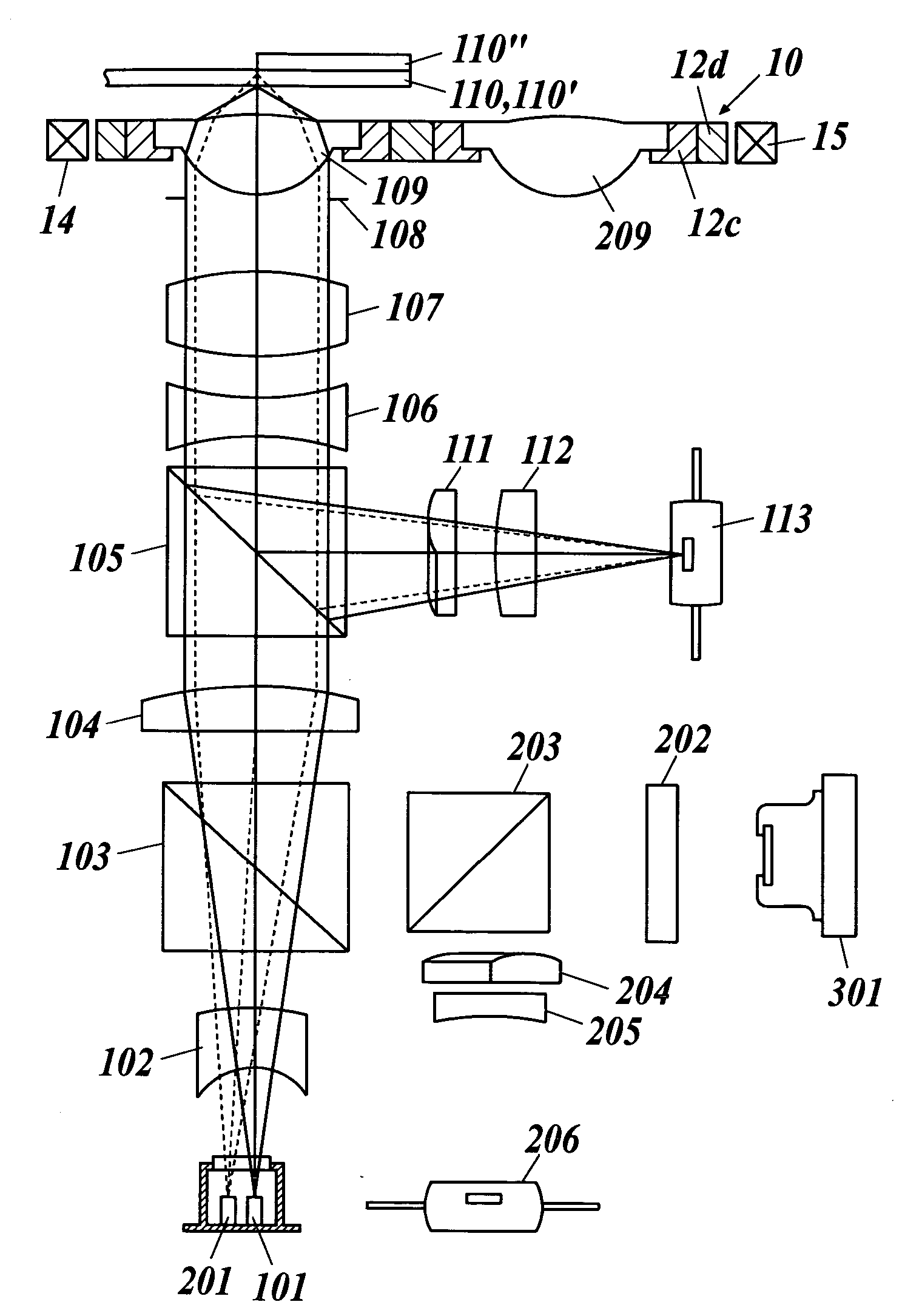
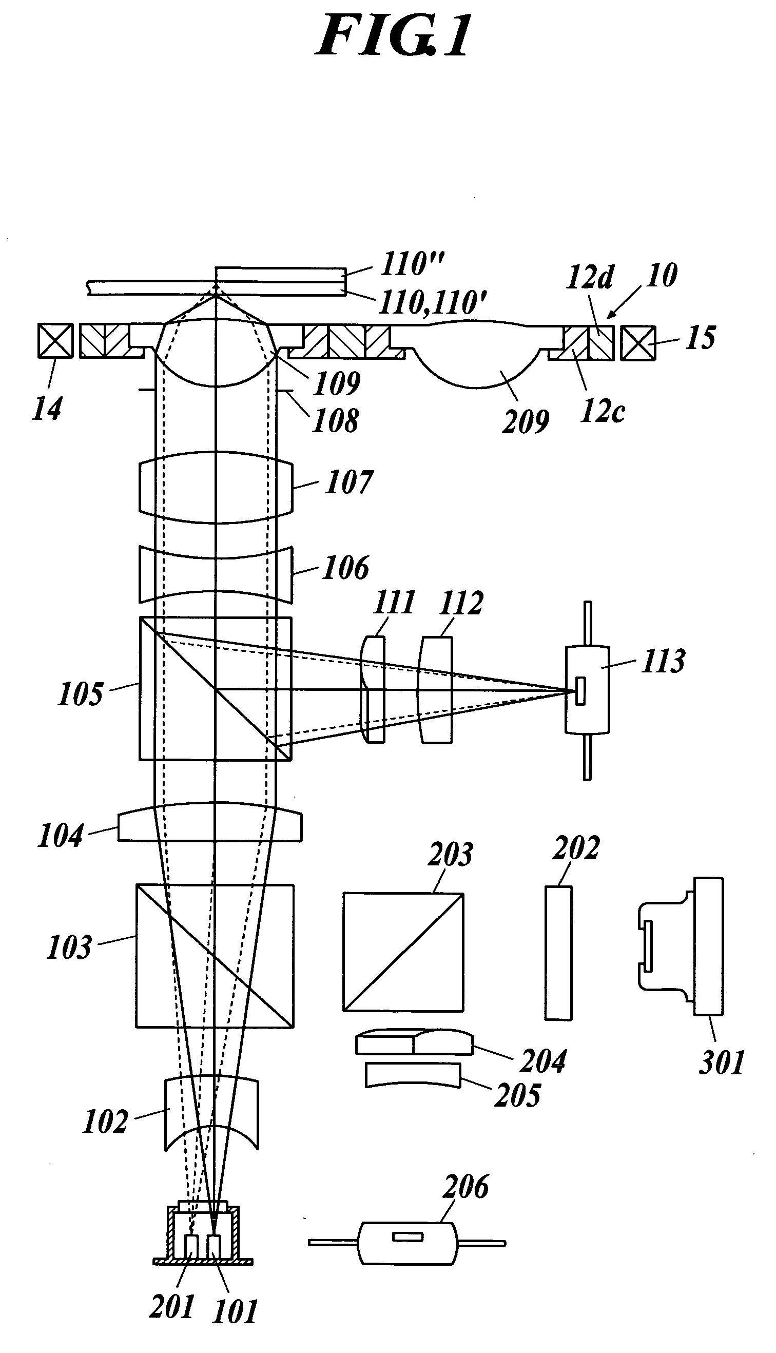
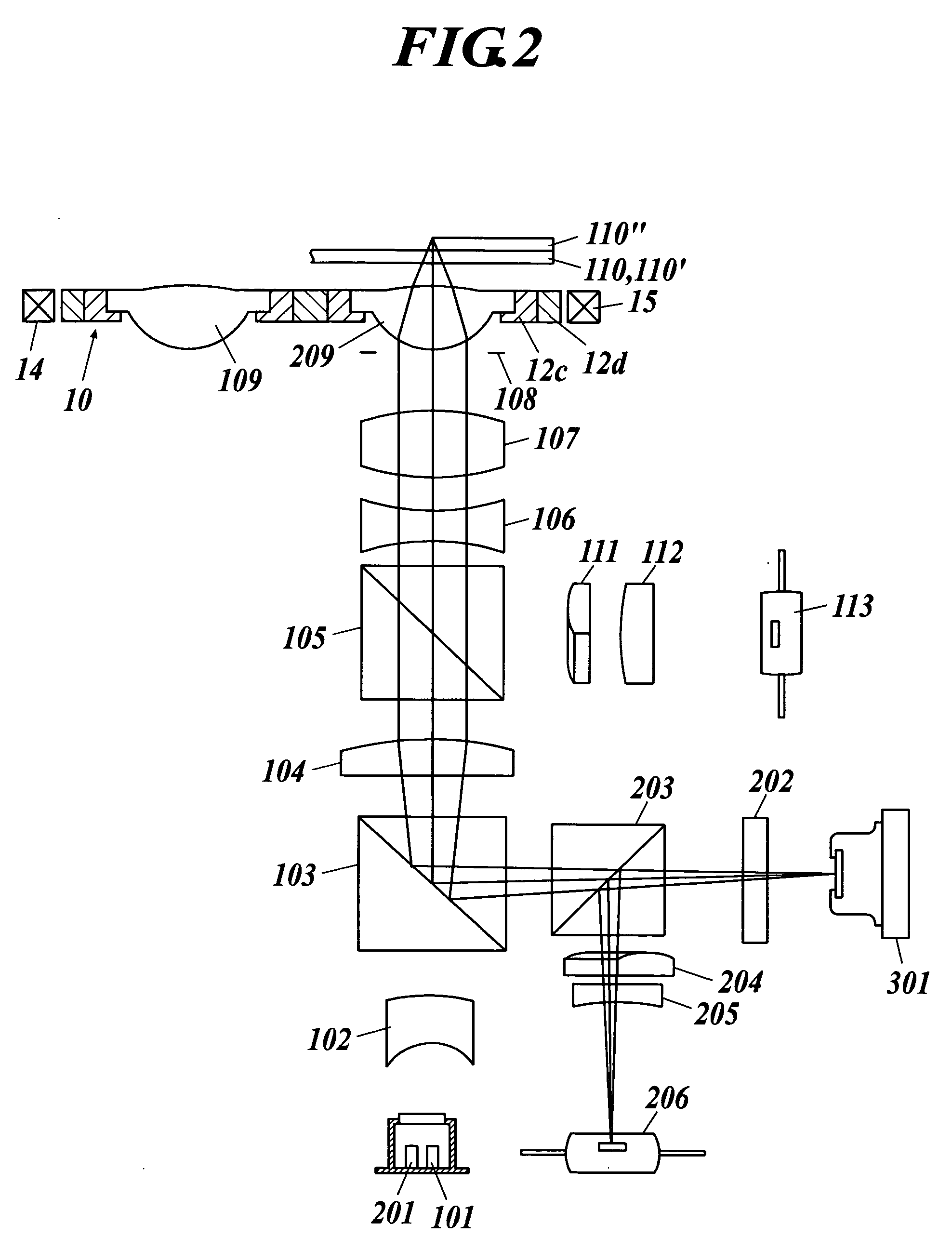
An optical pickup apparatus having first and second light sources emitting first and second light fluxes having wavelength of λ1 and λ2, respectively, an light-converging optical system including first and second objective optical elements, and a lens holder to hold the first and second objective optical elements. When the optical pickup apparatus converges the first or the second light flux onto first or second information recording surface of first or second information recording medium through one protective substrate, which has a thickness of t1 or t2 and is provided on the first or second information recording surface, with utilizing the first or second objective optical element for conducting information recording and / or information reproducing of the first or second information recording medium, a variation of each of a coma aberration and an astigmatism is not more than 0.02 λ1 rms or 0.02 λ2 rms, respectively.

Description

TECHNICAL FIELD [0001] The present invention relates to an optical pickup apparatus, and more particularly to an optical pickup apparatus capable of information recording and / or information reproducing to different optical information recording media by converging light fluxes emitted from light sources having light source wavelengths different from each other through either of two objective optical elements. BACKGROUND ART [0002] In recent years, research and development of a high density optical disc system capable of information recording and / or information reproducing using a blue-violet semiconductor laser having a wavelength of about 400 nm have been rapidly advancing. As an example, in an optical disc performing information recording and / or information reproducing in the specifications of a numerical aperture (NA) of 0.85 and a light source wavelength of 405 nm (hereinafter such an optical disc is referred to as a “high density Digital Versatile Disc (DVD)” in the present spe...

Claims


Application Information

Patent Timeline
Patent Type & Authority Applications(United States)
IPC IPC(8): G11B7/00
CPCG11B7/1275G11B7/1353G11B7/1374G11B7/1378G11B2007/13727G11B7/13925G11B2007/0006G11B2007/0013G11B7/13922
Inventor ATARASHI, YUICHIKOJIMA, TAKESHINOGUCHI, KAZUTAKA
Owner KONICA MINOLTA OPTO
Learn More