Photocurrent sensing circuit converting an illumination of visible light into an electric signal as well as photosensor and electronic device with the photocurrent sensing circuit

a photocurrent sensing circuit and visible light technology, applied in the field of photocurrent sensing circuit converting an illumination of visible light into an electric signal, can solve the problems of increasing the manufacturing cost of the photocurrent sensing circuit, affecting the battery life, and high environmental load, so as to reduce the cost and suppress the temperature-change of output current

Inactive Publication Date: 2008-05-08
SHARP KK
View PDF7 Cites 5 Cited by
  • Summary
  • Abstract
  • Description
  • Claims
  • Application Information

AI Technical Summary

Benefits of technology

[0033]An object of the invention is to provide a photocurrent sensing circuit that suppresses temperature-changes in output current and can reduce a cost as well as a photosensor and an electronic circuit that are provided with the same.

Problems solved by technology

In recent years, there has been a problem relating to use and the like of substances causing high environmental loads, and restrictions are being introduced on use of the CdS cells containing cadmium sulfide as a major component.
When light of a high illumination such as direct sunlight illumination enters the sensor, it outputs a current of several milliamperes or more, and this affects a battery life.
Further, for providing thermal voltage Vt and resistance RE having the temperature coefficients equal to each other, it is necessary to integrate a special temperature measuring resistance having the same temperature coefficient as thermal voltage Vt over a wide temperature range, which increases a manufacturing cost of the photocurrent sensing circuit.

Method used


Image

  • Photocurrent sensing circuit converting an illumination of visible light into an electric signal as well as photosensor and electronic device with the photocurrent sensing circuit
  • Photocurrent sensing circuit converting an illumination of visible light into an electric signal as well as photosensor and electronic device with the photocurrent sensing circuit
  • Photocurrent sensing circuit converting an illumination of visible light into an electric signal as well as photosensor and electronic device with the photocurrent sensing circuit

Examples


first embodiment

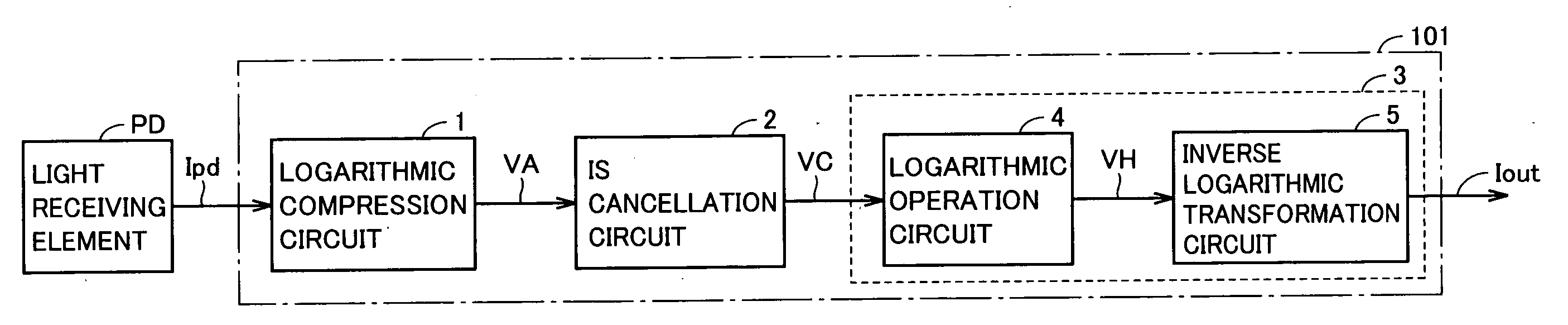
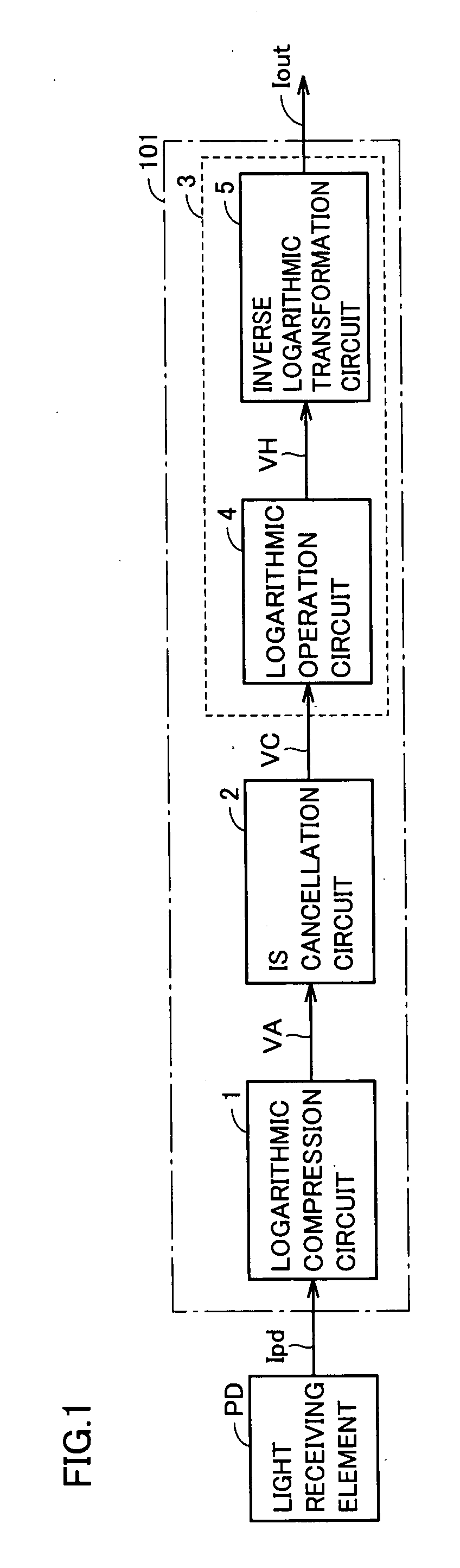
[0056]FIG. 1 is a block diagram showing a structure of a photocurrent sensing circuit according to a first embodiment of the invention.

[0057]Referring to FIG. 1, a photocurrent sensing circuit 101 includes a logarithmic compression circuit (first logarithmic compression circuit) 1, an Is cancellation circuit 2 and a Vt cancellation circuit 3. Vt cancellation circuit 3 includes a logarithmic operation circuit 4 and an inverse logarithmic transformation circuit 5. Voltages VA-VH to be described below correspond to voltages Va-Vh in a photocurrent sensing circuit according to a second embodiment of the invention, respectively.

[0058]A light receiving element PD receives external light to output a photocurrent Ipd proportional to a quantity of the received light.

[0059]Logarithmic compression circuit 1 includes a diode DA (not shown), logarithmically compresses photocurrent Ipd received from light receiving element PD using diode DA and thereby converts it into a voltage VA. When Vt repre...

second embodiment

[0071]This embodiment relates to an example of a specific circuit structure of the photocurrent sensing circuit according to the first embodiment of the invention.

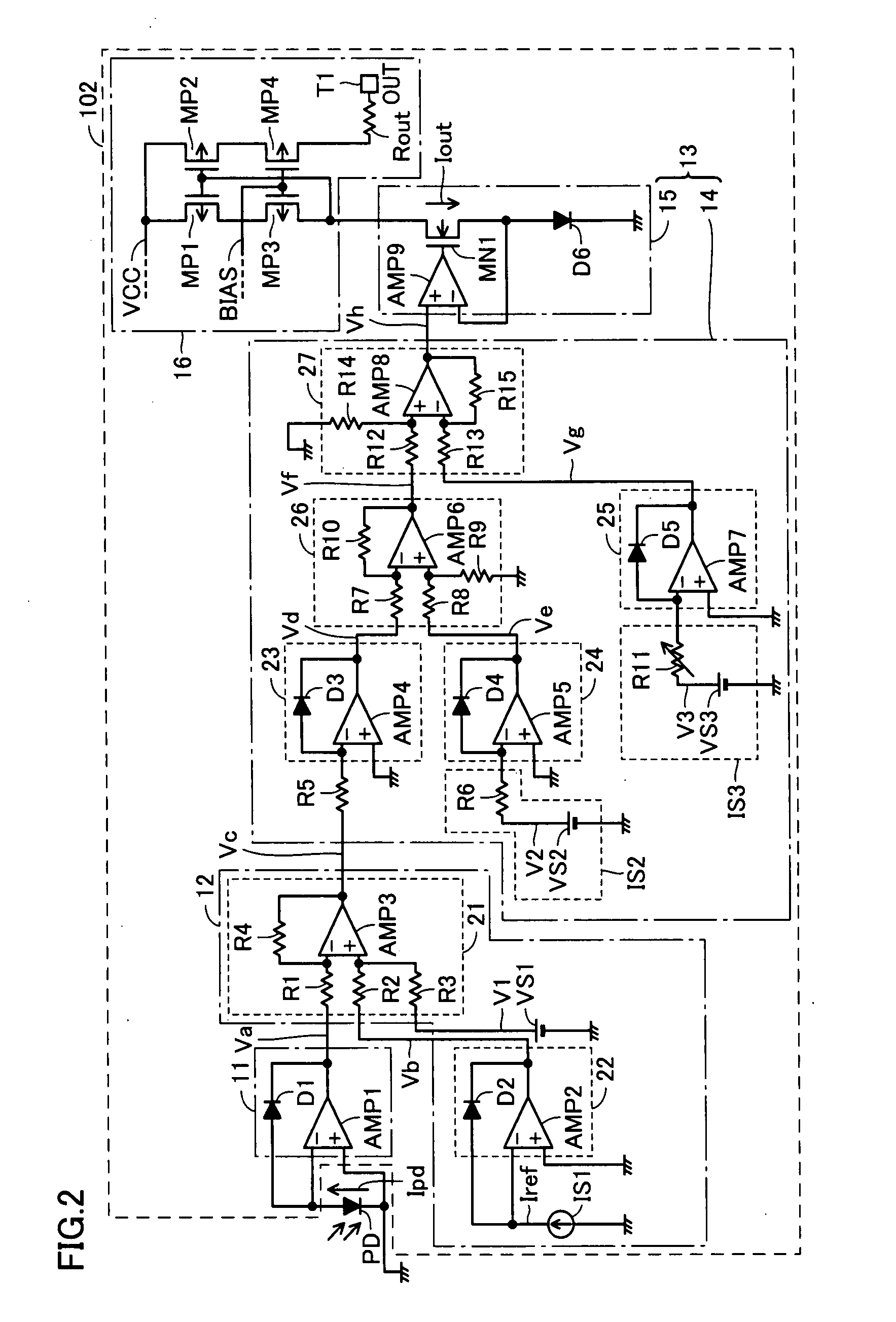
[0072]FIG. 2 is a circuit diagram showing a structure of a photocurrent sensing circuit according to the second embodiment of the invention.

[0073]Referring to FIG. 2, a photocurrent sensing circuit 102 includes a logarithmic compression circuit (first logarithmic compression circuit) 11, an Is cancellation circuit 12, a Vt cancellation circuit 13 and an output circuit 16. Vt cancellation circuit 13 includes a logarithmic operation circuit 14 and an inverse logarithmic transformation circuit 15. Logarithmic compression circuit 11 includes a diode D1 and an operational amplifier AMP1.

[0074]Is cancellation circuit 12 includes an operation circuit (first operation circuit) 21, a logarithmic compression circuit (second logarithmic compression circuit) 22, a constant current supply circuit (first current supply circuit) IS1 and ...

third embodiment

[0122]A third embodiment relates to a photocurrent sensing circuit that is different from the photocurrent sensing circuit of the second embodiment in reference voltages of the operational amplifier and the like. Details other than those described below are the same as those of the photocurrent sensing circuit according to the second embodiment.

[0123]FIG. 3 is a circuit diagram showing a structure of the photocurrent sensing circuit according to a third embodiment of the invention.

[0124]Referring to FIG. 3, a photocurrent sensing circuit 103 includes a logarithmic compression circuit (first logarithmic compression circuit) 31, an Is cancellation circuit 32, a Vt cancellation circuit 33, a Vref (reference voltage) cancellation circuit 37, an output circuit 36 and a reference voltage circuit Vref Vt cancellation circuit 33 includes a logarithmic operation circuit 34 and an inverse logarithmic transformation circuit 35. Logarithmic compression circuit 31 includes a PNP transistor QP1 a...


PUM


Abstract

A photocurrent sensing circuit includes a logarithmic compression circuit; a cancellation circuit logarithmically compressing a current substantially equal in temperature coefficient of the photocurrent to convert the same into a voltage, and performing an addition or a subtraction on the converted voltage and a voltage converted from a photocurrent by logarithmically compression; a logarithmic operation circuit logarithmically compressing the voltage received from the cancellation circuit to produce a first voltage, logarithmically compressing a voltage proportional to a thermal voltage of the photocurrent to produce a second voltage, logarithmically compressing a current having thermal dependence of nearly zero to produce a third voltage and performing an addition or a subtraction of each of the second and third voltages with respect to the first voltage to produce a fourth voltage; and an inverse logarithmic transformation circuit performing inverse logarithmic transformation on the fourth voltage to output a current.

Description

[0001]This nonprovisional application is based on Japanese Patent Application No. 2006-303062 filed with the Japan Patent Office on Nov. 8, 2006, the entire contents of which are hereby incorporated by reference.BACKGROUND OF THE INVENTION[0002]1. Field of the Invention[0003]The present invention relates to a photocurrent sensing circuit converting an illumination of visible light into an electric signal as well as a photosensor and an electronic device that are provided with the photocurrent sensing circuit, and particularly to a photocurrent sensing circuit that has spectral sensitivity characteristics close to human visual sensitivity characteristics as well as a photosensor and an electronic device provided with the same.[0004]2. Description of the Background Art[0005]As typical examples of photosensors for visible light, there are two kinds of sensors of silicon photodiodes and CdS (Cadmium Sulfide) cells are. Since the silicon photodiode has small sizes, high responsibility an...

Claims


Application Information

Patent Timeline
Patent Type & Authority Applications(United States)
IPC IPC(8): H02M7/00
CPCG01J1/44G01J1/18Y10S323/907
Inventor SHIMIZU, TAKAYUKI
Owner SHARP KK
Why Eureka
Try Eureka