Battery-driven power source apparatus

a power source and battery technology, applied in the field of battery power supply systems, can solve the problems of increasing the dimensions of the battery power supply system itself, not being suitable for mounting in a battery car, and being more limited, so as to reduce the overall temperature variation of the battery module groups and increase the temperature variation

Inactive Publication Date: 2007-08-28
HONDA MOTOR CO LTD
View PDF7 Cites 5 Cited by
  • Summary
  • Abstract
  • Description
  • Claims
  • Application Information

AI Technical Summary

Benefits of technology

[0007]An object of the present invention is to provide a battery power supply system that can suppress the overall temperature variation across the battery module groups by simple means such as changing the manner in which the battery module groups are arranged.
[0009]In accordance with this arrangement, the cooling air, which has been introduced from between two adjacent rod-shaped battery modules of the first battery module group, has its entry between the rod-shaped battery modules of the first battery module group and the adjacent rod-shaped battery modules of the second battery module group suppressed, and the cooling air instead flows straight on. Although this reduces the extent of cooling of the first and second battery module groups, the cooling air, whose temperature increase has as a result been suppressed, can increase the extent of cooling of third and subsequent battery module groups, thereby suppressing the overall temperature variation of the battery module groups. Furthermore, since no rectifying plate is used and the pressure loss of the cooling air passing through the box is small, the suction fan can have a small size, thus reducing the cost of the battery power supply system. In this way, all of the above-mentioned defects of the conventional arrangements can be eliminated.
[0011]Another object of the present invention is to provide a battery power supply system that can greatly suppress the overall temperature variation of the battery module groups by adding a new restriction requirement to the structural arrangement of the rod-shaped battery modules.
[0013]In accordance with this arrangement, the suppression of preferential cooling of the first and second rod-shaped battery module groups by setting a>b can be further promoted, thereby reducing the overall temperature variation of the battery module groups. However, when L / N is<0.5 or>2.0, the temperature variation increases. The ratio L / N is preferably 0.5<L / N<2.0.

Problems solved by technology

That is, if the gap a is too large, the dimensions of the battery power supply system itself increase, and it is not suitable for mounting in a battery car, etc.
On the other hand, if the gap b is too small, the first and second battery module groups are too close to each other, the areas of the outer peripheral faces that are exposed to the cooling air are more limited, the extent of the cooling thereof is decreased, and the overall temperature variation of the battery module groups cannot be suppressed.

Method used


Image

  • Battery-driven power source apparatus
  • Battery-driven power source apparatus
  • Battery-driven power source apparatus

Examples


embodiment i

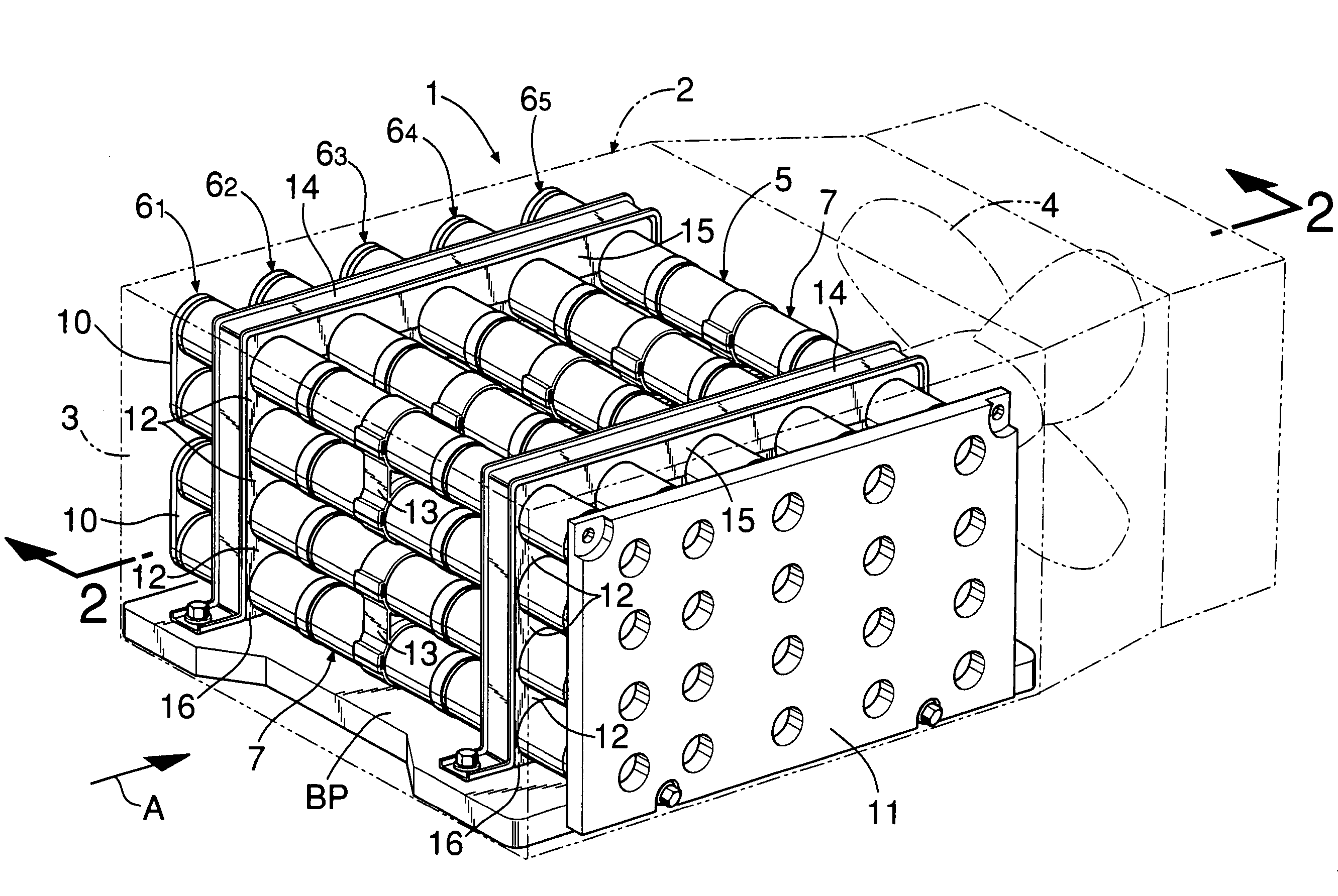
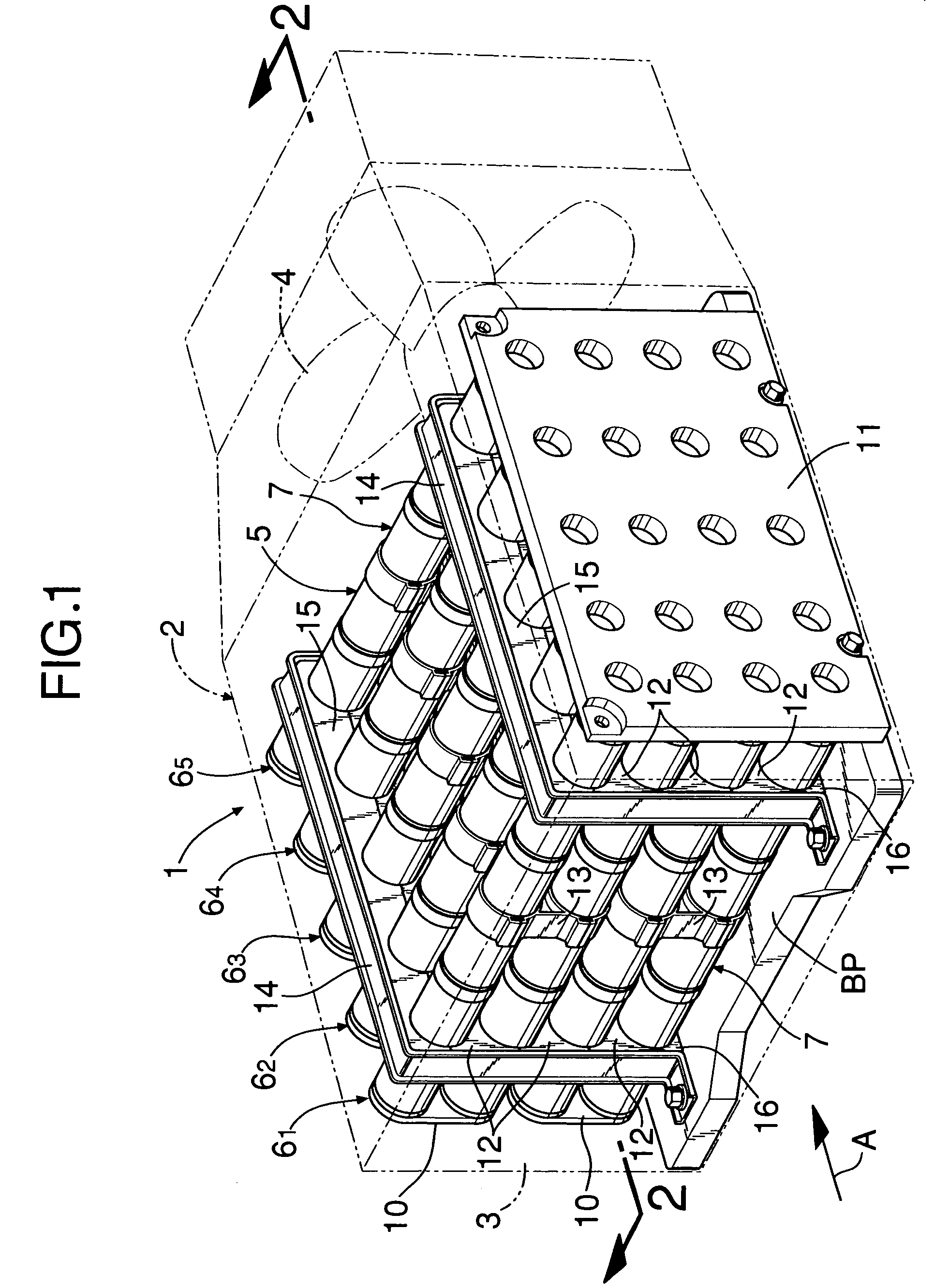
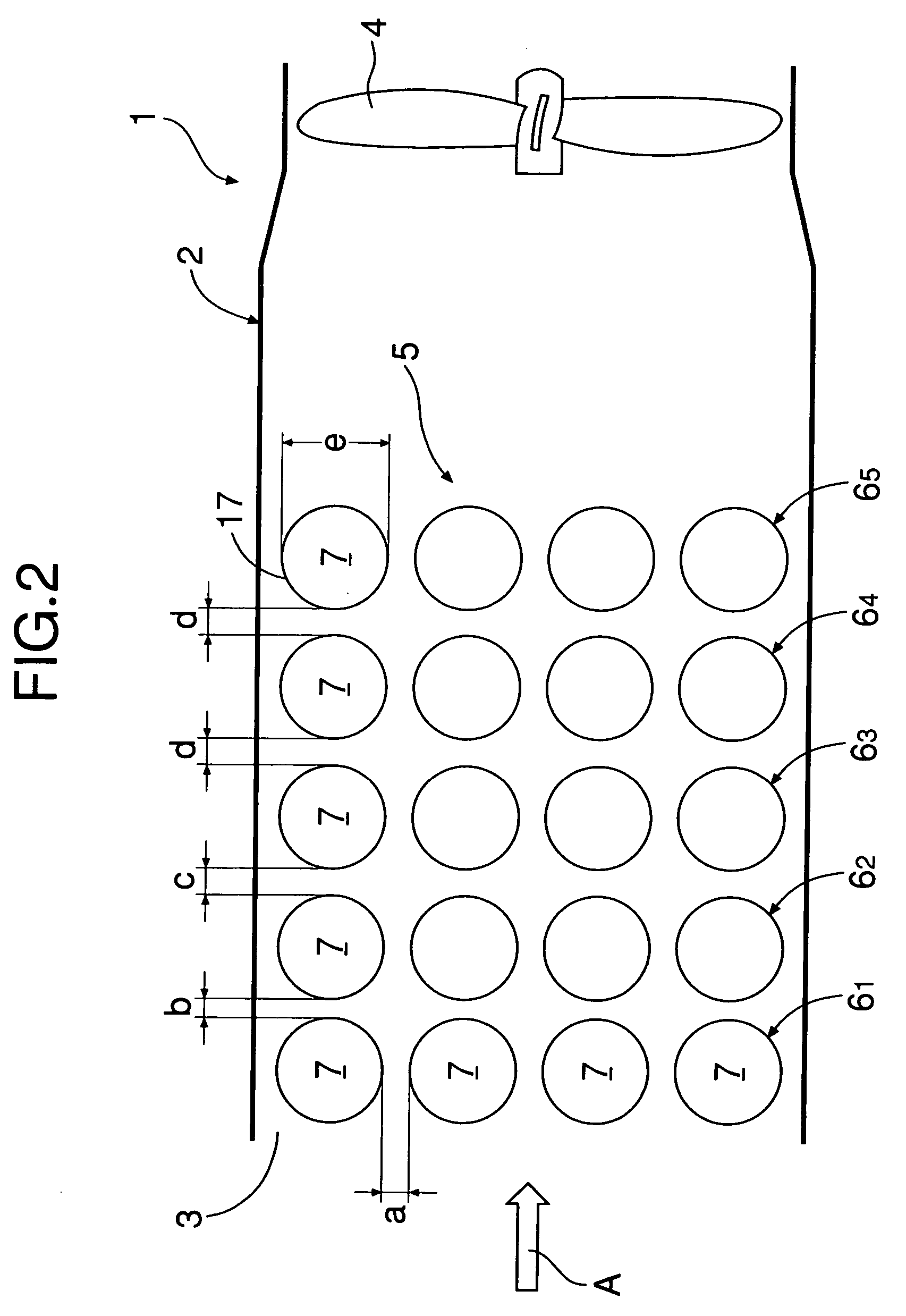
[0034]In FIGS. 1 and 2, a battery power supply system 1 includes a synthetic resin box 2, and the box 2 has a cooling air inlet 3 on one end face thereof and a suction fan 4 within a section at the other end (the box 2 can be made of metal). Within the box 2, a battery assembly 5 is housed between the cooling air inlet 3 and the suction fan 4, that is, in an intermediate section within the box 2. The battery assembly 5 includes a plurality, five in this embodiment, of battery module groups, that is, first to fifth battery module groups 61 to 65, which are arranged parallel to each other at intervals along a cooling air flow direction A. As shown in FIG. 3, each of the battery module groups 61 to 65 is formed from a plurality, four in this embodiment, of rod-shaped battery modules 7, which are arranged, within an imaginary plane P1 intersecting the cooling air flow direction A, at equal intervals with the axes thereof intersecting the cooling air flow direction A. The axes of one rod...

embodiment ii

[0043]In FIGS. 8 and 9, a battery power supply system 1 includes a synthetic resin box 2, and the box 2 has a cooling air inlet 3 on one end face thereof and a suction fan 4 within a section at the other end (the box 2 can be made of metal). Within the box 2, a battery assembly 5 is housed between the cooling air inlet 3 and the suction fan 4, that is, in an intermediate section within the box 2. The battery assembly 5 comprises a plurality, five in this embodiment, of battery module groups, that is, first to fifth battery module groups 61 to 65, which are arranged parallel to each other at intervals along a cooling air flow direction A. As shown in FIG. 10, each of the battery module groups 61 to 65 is formed from a plurality, four in this embodiment, of rod-shaped battery modules 7, which are arranged, within an imaginary plane P1 intersecting the cooling air flow direction A, at equal intervals with the axes thereof intersecting the cooling air flow direction A. The axes of one r...


PUM

PropertyMeasurementUnit
outer diameteraaaaaaaaaa
flow rateaaaaaaaaaa
temperatureaaaaaaaaaa

Abstract

A battery power supply system (1) for suppressing the overall temperature variation of a plurality of battery module groups (61 to 65) includes a box (2) having a cooling air inlet (3) on one end face and a suction fan (4) within a section at the other end, and a battery assembly (5) installed in an intermediate section within the box (2). The battery assembly (5) includes a plurality of battery module groups (61 to 65). Each of the battery module groups (61 to 65) includes a plurality of rod-shaped battery modules (7). When a gap between outer peripheral faces of two adjacent rod-shaped battery modules (7) of the first battery module group (61), which is closest to the cooling air inlet (3), is a, and a gap between the outer peripheral face of the rod-shaped battery modules (7) of the first battery module group (61) and the outer peripheral face of the adjacent rod-shaped battery modules (7) of the second battery module group (62) is b, the ratio a / b of the gaps a and b is set so that 1.0<a / b≦2.0.

Description

CROSS-REFERENCE TO RELATED APPLICATION[0001]This application is a National Stage entry of International Application Number PCT / JP02 / 11010, filed Oct. 23, 2002. The disclosure of the prior application is hereby incorporated herein in its entirety by reference.FIELD OF THE INVENTION[0002]The present invention relates to a battery power supply system and, in particular, one that includes a battery assembly and is mounted as a power source in a battery car, a hybrid car, a fuel cell car, etc. The battery concept referred to here includes those with various types of storage functions such as high capacity electric double-layer capacitors as well as primary batteries and secondary batteries.BACKGROUND ART[0003]As this type of battery power supply system there is a conventionally known arrangement that includes a box having a cooling air inlet on one end face and a suction fan within a section at the other end, and a battery assembly housed within the box. The battery assembly is formed fr...

Claims


Application Information

Patent Timeline
Patent Type & Authority Patents(United States)
IPC IPC(8): H01M10/50B60K1/04H01M50/213
CPCB60K1/04H01M2/1072H01M10/5067H01M10/503H01M10/5036H01M10/5059H01M10/5004B60K2001/005H01M2/105H01M10/6563H01M10/6557H01M10/643H01M10/651H01M10/613Y02E60/10H01M50/213
Inventor WATANABE, KENJISATO, NOBORUKIKUCHI, JUNICHINAGANUMA, ATSUHIROOHYA, SATOYOSHI
Owner HONDA MOTOR CO LTD
Why Eureka
Try Eureka