Electrostatic chuck

a technology of electrostatic chuck and chuck body, which is applied in the direction of electrical equipment, chemistry apparatus and processes, ceramic layered products, etc., can solve the problems of leakage current flow in the equipment side and the difficulty of simultaneously satisfying such requirements, and achieve the effect of improving the adhesion between the second support plate and the layers proximal to the second support pla

Active Publication Date: 2019-01-17
TOTO LTD
View PDF32 Cites 5 Cited by
  • Summary
  • Abstract
  • Description
  • Claims
  • Application Information

AI Technical Summary

Benefits of technology

[0067]According to the electrostatic chuck, the adhesion between the second support plate and the layers proximal to the second

Problems solved by technology

Also, when the RF voltage is applied, a leakage current flows in the equ

Method used


Image

  • Electrostatic chuck
  • Electrostatic chuck
  • Electrostatic chuck

Examples


Embodiment Construction

[0100]Embodiments of the invention will now be described with reference to the drawings. Similar components in the drawings are marked with the same reference numerals; and a detailed description is omitted as appropriate.

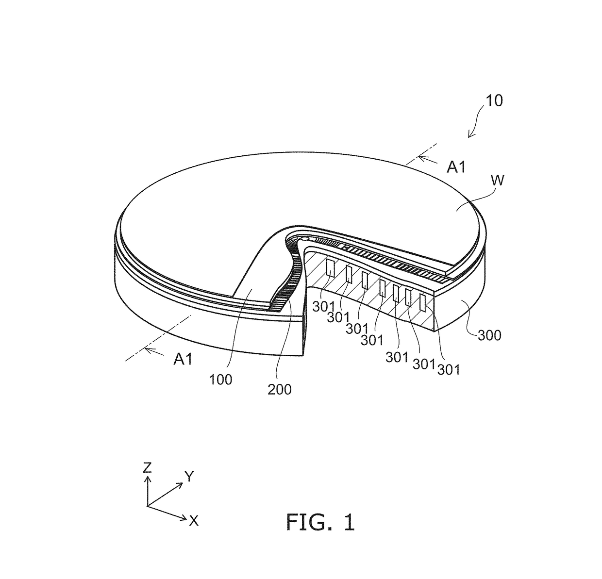
[0101]FIG. 1 is a schematic perspective view illustrating an electrostatic chuck according to the embodiment.

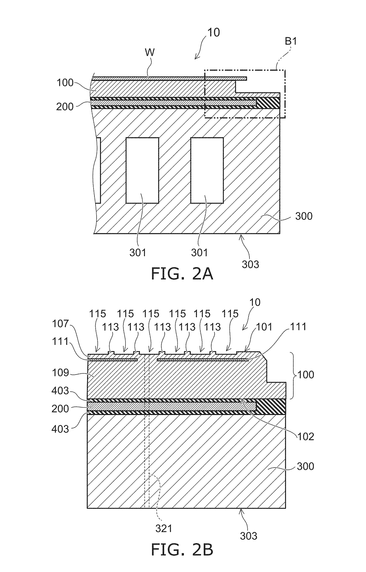
[0102]FIG. 2A and FIG. 2B are schematic cross-sectional views illustrating the electrostatic chuck according to the embodiment.

[0103]In FIG. 1, a cross-sectional view of a portion of the electrostatic chuck is illustrated for convenience of description. FIG. 2A is, for example, a schematic cross-sectional view of an A1-A1 cross section illustrated in FIG. 1. FIG. 2B is an enlarged schematic view of region B1 illustrated in FIG. 2A.

[0104]The electrostatic chuck 10 according to the embodiment includes a ceramic dielectric substrate 100, a heater plate 200, and a base plate 300.

[0105]The ceramic dielectric substrate 100 is provided at a position separated from ...


PUM

PropertyMeasurementUnit
Thicknessaaaaaaaaaa
Electrical conductivityaaaaaaaaaa
Sizeaaaaaaaaaa

Abstract

An electrostatic chuck includes a ceramic dielectric substrate, a base plate, and a heater plate. The heater plate is provided between the ceramic dielectric substrate and the base plate. The heater plate includes first and second support plates, first and second resin layers, and a heater element. Each of the first and second resin layers is provided between the first support plate and the second support plate. The heater element includes first and second electrically conductive portions. The first electrically conductive portion is provided between the first resin layer and the second resin layer. The second electrically conductive portion is separated from the first electrically conductive portion in an in-plane direction. The first resin layer contacts the second resin layer between the first electrically conductive portion and the second electrically conductive portion.

Description

CROSS-REFERENCE TO RELATED APPLICATIONS[0001]This application is a continuation application of International Application PCT / JP2017 / 009894, filed on Mar. 13, 2017. This application also claims priority to Japanese Application No. 2016-049902, filed on Mar. 14, 2016, and Japanese Application No. 2017-010353, filed on Jan. 24, 2017; the entire contents of each are incorporated herein by reference.FIELD OF THE INVENTION[0002]Embodiments of the invention relate generally to an electrostatic chuck.BACKGROUND OF THE INVENTION[0003]An electrostatic chuck is used to attract and hold a processing object such as a semiconductor wafer, a glass substrate, etc., inside a plasma processing chamber that performs etching, CVD (Chemical Vapor Deposition), sputtering, ion implantation, ashing, etc. The electrostatic chuck applies electrical power for electrostatic attraction to a built-in electrode and attracts and holds a substrate such as a silicon wafer, etc., by an electrostatic force.[0004]In re...

Claims


Application Information

Patent Timeline
IPC IPC(8): H01L21/683B32B18/00
CPCB32B18/00H01L21/6833H01L21/67103H01L21/6831H01L21/6835
Inventor UEFUJI, JUMPEISASAKI, HITOSHIYAMAGUCHI, KOSUKEMAEHATA, KENGOYOSHII, YUICHI
Owner TOTO LTD
Why Eureka
Try Eureka