
Touch trigger measurement probe

A technology for measuring probes and stylus, which is applied in the field of measuring probes, can solve problems such as reducing measurement accuracy, and achieve the effect of improving performance

Inactive Publication Date: 2013-08-28
RENISHAW PLC
View PDF3 Cites 2 Cited by
  • Summary
  • Abstract
  • Description
  • Claims
  • Application Information

AI Technical Summary

Problems solved by technology

Said increased pretravel reduces measurement accuracy in various ways; for example, errors may occur due to stylus slippage

Method used


Image

  • Touch trigger measurement probe
  • Touch trigger measurement probe
  • Touch trigger measurement probe

Examples


Embodiment Construction

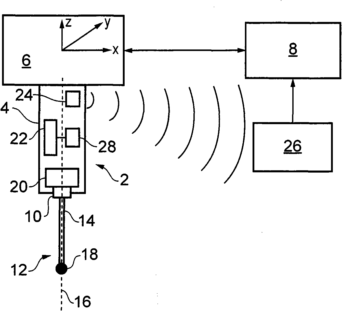
[0035] refer to figure 1 , shows a touch trigger measuring probe 2 having a probe housing or body 4 attached to a rotatable spindle 6 of a machine tool. The main shaft 6 is attached to a machine head (not shown) which is movable around the machine envelope along three mutually orthogonal axes (x, y, z). The movement of the spindle is controlled by a computer numerical controller 8 . The position of the spindle 6 is measured by a position encoder (not shown) and this position information is provided to the CNC 8 .

[0036] The measuring probe 2 has a stylus holder 10 to which a stylus 12 is attached by a screw connection. The stylus 12 includes a stem 14 for attachment to an object mounted to the machine bed, such as a workpiece or calibration artefact, extending along a longitudinal axis 16 and terminating in a stylus tip or ball 18 .

[0037] The stylus holder 10 is connected to the probe housing 4 via a strain sensor 20 . In this example, the strain sensor 20 comprises t...


PUM


Abstract

A measurement probe, for a co-ordinate positioning apparatus such as a machine tool, is described that includes a stylus holder that is deflectably mounted to a probe housing. One or more sensors are provided for sensing deflection of the stylus holder relative to the probe housing. A processor is included for producing a trigger signal when the deflection sensed by the one or more sensors meets a trigger condition, such as a deflection threshold. The probe also includes an accelerometer for measuring acceleration of the measurement probe. The trigger condition applied by the processor is alterable, during use, in response to the acceleration measured by the accelerometer. In this manner, false triggering can be suppressed.

Description

technical field [0001] The invention relates to a measuring probe for a coordinate positioning device, in particular to a touch trigger measuring probe which can be installed in the spindle of a machine tool. Background technique [0002] Touch trigger measuring probes are known for installation in machine tool spindles. A typical measurement probe of this type includes a workpiece contact stylus that is deflectable relative to the body or housing of the probe. One or more sensors are provided to measure the deflection of the stylus relative to the stylus body, and whenever a certain amount of stylus deflection occurs, a so-called trigger signal is issued to indicate that the stylus has come into contact with the workpiece. This trigger signal is supplied to the machine tool controller, which reads the position of the machine spindle when the trigger signal is sent, thereby obtaining the coordinates of a point on the surface of the measured workpiece. [0003] Examples of ...

Claims


Application Information

Patent Timeline
Patent Type & Authority Patents(China)
IPC IPC(8): G01B7/012G01B21/04
CPCG01B7/012G01B2210/58G01B21/047G01B5/012
Inventor 迈克尔·约翰·伍尔德里奇彼得·肯尼思·赫利尔罗伯特·查尔斯·多利埃·乌姆弗勒维尔
Owner RENISHAW PLC
Learn More