Motor/transmission unit and modular system

A transmission device and motor technology, applied in the direction of electromechanical devices, electrical components, electric components, etc., can solve problems such as the limitation of the use of common parts

Inactive Publication Date: 2011-02-09
ROBERT BOSCH GMBH
View PDF0 Cites 2 Cited by
  • Summary
  • Abstract
  • Description
  • Claims
  • Application Information

AI Technical Summary

Problems solved by technology

This leads to a very limited use of common parts in the motor-gear unit used, which leads to only a very limited reduction in product costs

Method used


Image

  • Motor/transmission unit and modular system
  • Motor/transmission unit and modular system
  • Motor/transmission unit and modular system

Examples


Embodiment Construction

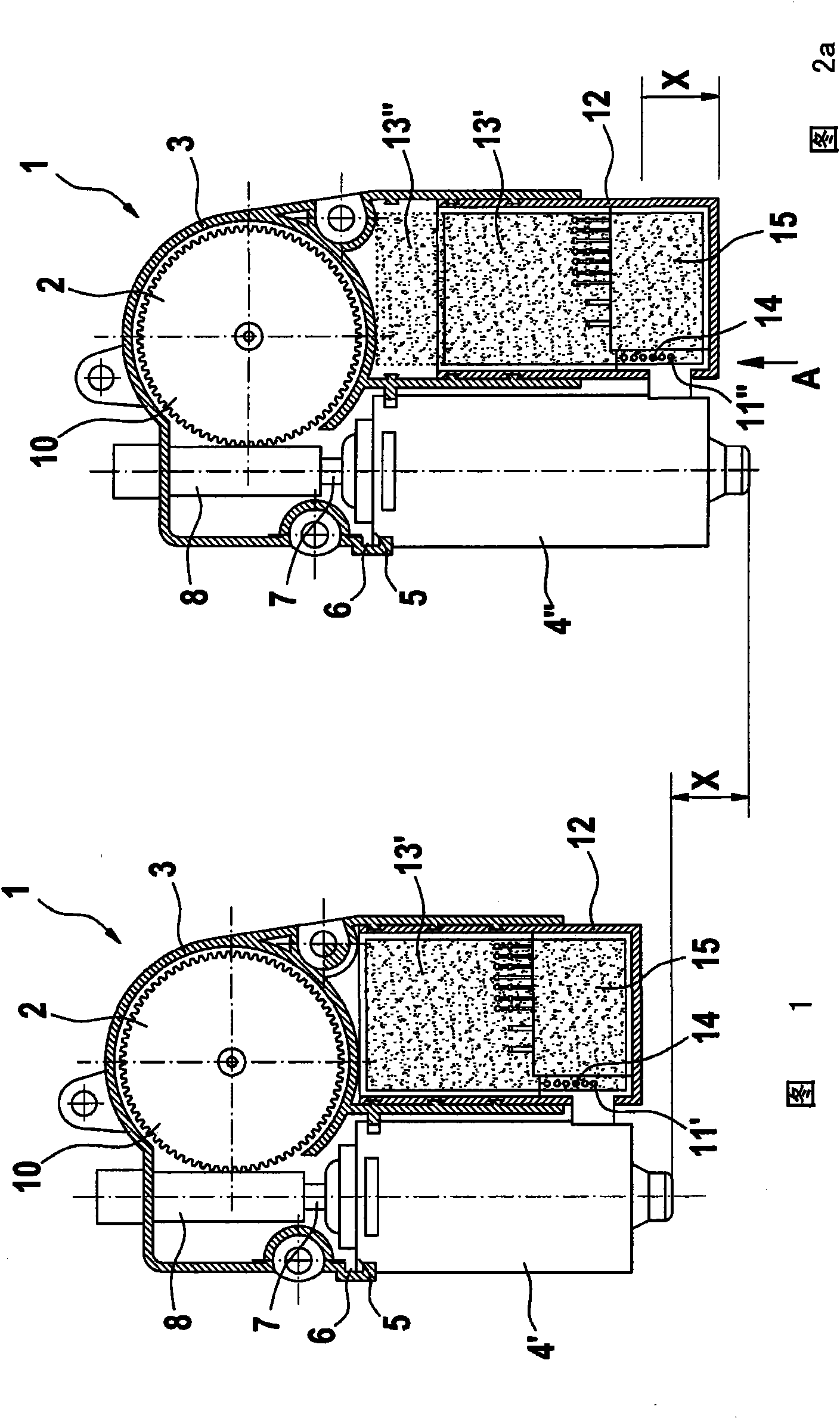
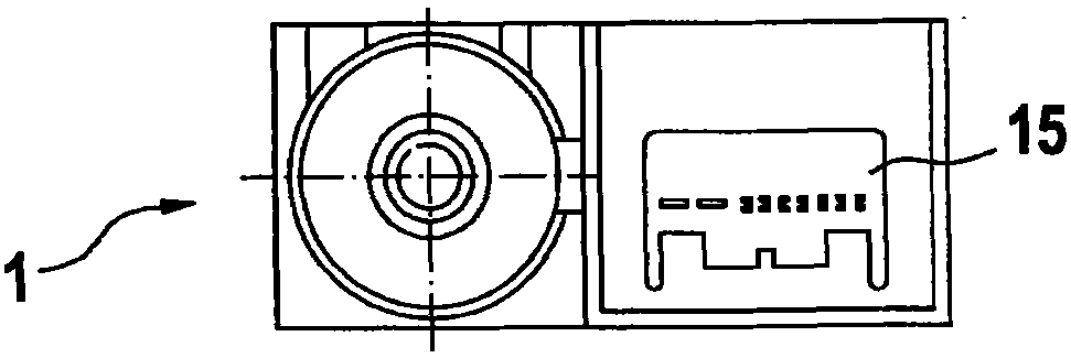
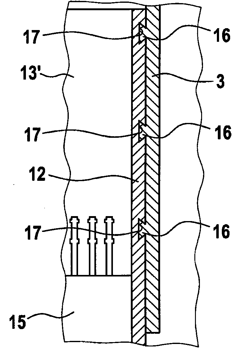
[0029] exist Figures 1 to 2b A modular system of motor-gear units 1 is shown in . The modular system comprises a gear 2 designed as a worm gear, which has a uniform gear housing 3 . Motor housings 4 ′ and 4 ″ of different sizes, here two different lengths, can be fastened to the transmission housing 3 . For this purpose, the two motor housings 4 ′, 4 ″ have a single motor housing The connection 5 is used for alternative fastening to a uniform transmission housing connection 6 . In the illustrated embodiment of the modular system, the transmission 3 comprises a transmission worm 8 connected in a rotationally fixed manner to the motor shaft 7 , which meshes with a driven gear 10 , and the driven gear 10 in turn drives mechanisms not shown, such as for adjusting the window glass, the sliding sunroof or the car seat.

[0030] The lengths, ie the axial extensions, of the motor housings 4', 4" differ from each other by a distance X. The distance X is also used to electrically co...


PUM


Abstract

The invention relates to a motor/transmission unit (1), especially for automotive applications, comprising a printed circuit board housing (12) for a printed circuit board (13', 13''), which housing can be fixed to a transmission housing (3) and/or a motor casing (4', 4''). The motor/transmission unit is characterized in that the printed circuit board housing (12) can be fixed in different fastening positions. The invention further relates to a modular system.

Description

technical field [0001] The invention relates to a motor-gear unit according to the preamble of claim 1 and to a modular system according to the preamble of claim 7 . Background technique [0002] For automotive applications, for example for sliding sunroof drives, window adjustment drives or seat adjustment drives, motor-gear units of very different designs are known. Usually in the case of a motor-gear unit for a sliding sunroof drive, the sliding contact carrier (brush holder) is located on the printed circuit board of the motor-gear unit. It is advantageous here that the sliding contact carrier can be connected directly to the circuit board as a current-carrying element during the soldering process for fastening the active and passive electronic components to the circuit board. A disadvantage, however, is that the circuit board outline must be designed in such a way that a connection can be produced between the actual control electronics arranged on the circuit board and...

Claims


Application Information

Patent Timeline
Patent Type & Authority Applications(China)
IPC IPC(8): H02K5/22H02K11/00
CPCH02K7/1166H02K11/0084H02K5/225H02K11/38
Inventor R·布劳恩M·库佩兹克P·斯特伊尔S·迈尔S·赖希曼
Owner ROBERT BOSCH GMBH
Why Eureka
Try Eureka