
Aluminium wheel spinning mould ejector

A technology for ejectors and wheels, which is applied in the direction of pushing out equipment, etc., can solve the problems that the ejector of the lower die cannot return normally, produces aluminum chips, and scratches on the back cavity of the wheel spokes, and achieves the effect of improving the difficulty of returning to the position

Inactive Publication Date: 2011-02-16
CITIC DICASTAL
View PDF6 Cites 5 Cited by
  • Summary
  • Abstract
  • Description
  • Claims
  • Application Information

AI Technical Summary

Problems solved by technology

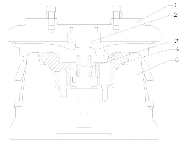
[0003] The structure of the existing lower die ejector is easy to make it slip with the wheel during the spinning process, and the wheel will be lost, which will scratch the back cavity of the wheel spoke, produce aluminum chips, and even cause the lower die ejector to stick. aluminum
The generated aluminum chips are easy to enter the gap between the lower die and the ejector of the lower die, so that the ejector of the lower die cannot return normally. When spinning again, the wheel spokes will also be seriously deformed, and the size of the spinning blank cannot be guaranteed. Require
Similarly, the sticking of aluminum on the ejector of the lower die will reduce its adhesion to the back cavity of the spoke and accelerate the slipping and deformation of the blank
[0004] The structure of the existing upper die ejector is easy to cause severe rigid impact between the upper die ejector and the center boss of the wheel during pressing; when the material is returned, the wheel and the ejector cannot be effectively separated, resulting in wheel deformation
[0005] The existing design of the guide copper bushing connected to the lower die ejector also scratches the wheel flange

Method used


Image

  • Aluminium wheel spinning mould ejector
  • Aluminium wheel spinning mould ejector
  • Aluminium wheel spinning mould ejector

Examples


Embodiment Construction

[0022] Technical scheme of the present invention is:

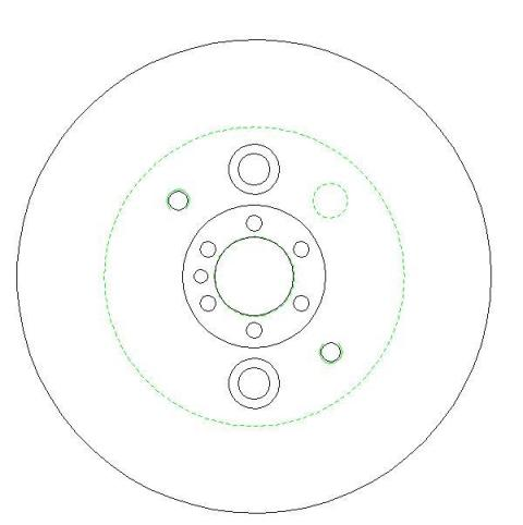
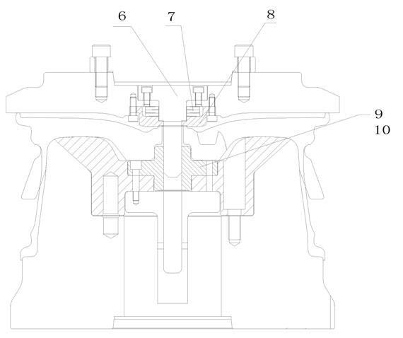
[0023] Change the opening position and angle of the 4 conical surfaces of the lower die ejector, change the middle part of the spokes of the prior art to the arc at the junction of the spokes and the rim, and change the angle from 50° to 45°.

[0024] Mill the anti-rotation groove at the joint surface with the back cavity of the spoke, and change the connection position between the ejector of the lower die and the guide copper sleeve;

[0025] Decompose the upper mold ejector into new upper mold ejector 8 and guide column 6. The new upper die ejector 8 is connected with the upper die bolts; the guide column 6 is connected with the upper die bolts to play a guiding role.

[0026] There is disc spring 7 between new upper die ejector 8 and upper die 1.

[0027] Described new lower die ejector 10 replaces lower die ejector 4, as figure 2 , Figure 4 shown. The new guide copper sleeve 9 replaces the guide copper sle...


PUM


Abstract

The invention discloses an aluminium wheel spinning mould ejector. The opening position and the angle of the conical surface of a low die ejector 4 are changed, the middle position of a spoke in the prior art is changed to the circular arc on the joint of the spoke and a rim, and the angle is changed to 45 degrees from 50 degrees. An anti-rotation groove is milled on the faying surface of a spoke back cavity, the connection position of the low die ejector and a guiding copper bush is changed, and an upper die ejector is decomposed into a new upper die ejector 8 and a guidepost 6. The upper die ejector 8 is connected with an upper die bolt, and the guidepost 6 is connected with the upper die bolt to perform the action of guiding. A disc spring 7 is arranged between the new upper die ejector 8 and an upper die 1.

Description

Technical field [0001] The invention involves a top material for a rotary mold, which specifically involves the upper and lower mold top materials of a rotation of a rotary aluminum alloy car. Background technique [0002] The top material is one of the important components in the rotary mold, which directly affects the forming process of the wheels.like figure 1 Show, the top material of the existing technology consists of the upper mold top and the lower mold top material. [0003] The structure of the existing bottom mold top material can easily slip with the wheels during the rotation process, and the wheel is thrown, which makes the wheel wheel spoke back cavity scratching, produced aluminum dandruff, and even causes the lower mold ceiling.aluminum.The generated aluminum chips are easily entered into the gap between the lower mold and the lower mold top material, so that the lower mold top material cannot be returned normally. When the wheel spoke is pressed, the wheel spoke...

Claims


Application Information

Patent Timeline
IPC IPC(8): B21D45/04
Inventor 常海平张立娟
Owner CITIC DICASTAL
Learn More