
Three-way locking device and three-way locking bolt electric control semi-automatic lock adopting electric control operation

A locking device and lock bolt technology, which is applied to construction locks, non-mechanical transmission-operated locks, construction and other directions, can solve the problems of complex action coordination, high manufacturing cost, failure of the locking device, etc., and achieves a simple structure. , The effect of low manufacturing cost and reduction of parts

Inactive Publication Date: 2011-02-16
GUANGZHOU GUUB TECH
View PDF8 Cites 14 Cited by
  • Summary
  • Abstract
  • Description
  • Claims
  • Application Information

AI Technical Summary

Problems solved by technology

However, the electric control lock also has the following defects: (1) There are many parts and components that make up the locking device, and the structure is very complicated; (2) Because there are many parts and their mutual cooperation, the manufacturing cost is high (3) It needs to consume more electric energy; (4) The action coordination relationship between the various parts is relatively complicated. If one of the parts is damaged, it is easy to cause the entire locking device to fail

Method used


Image

  • Three-way locking device and three-way locking bolt electric control semi-automatic lock adopting electric control operation
  • Three-way locking device and three-way locking bolt electric control semi-automatic lock adopting electric control operation
  • Three-way locking device and three-way locking bolt electric control semi-automatic lock adopting electric control operation

Examples


Embodiment Construction

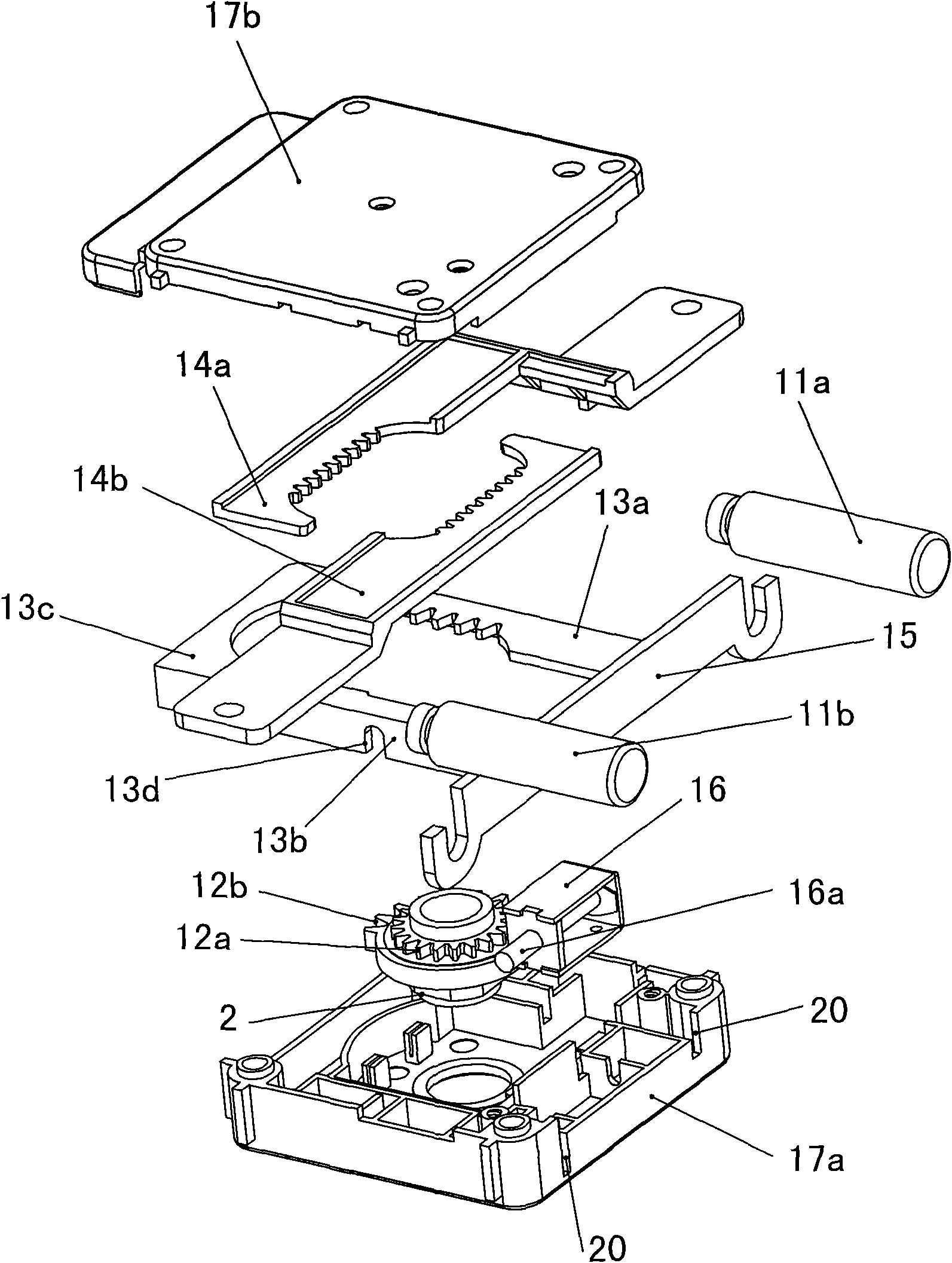
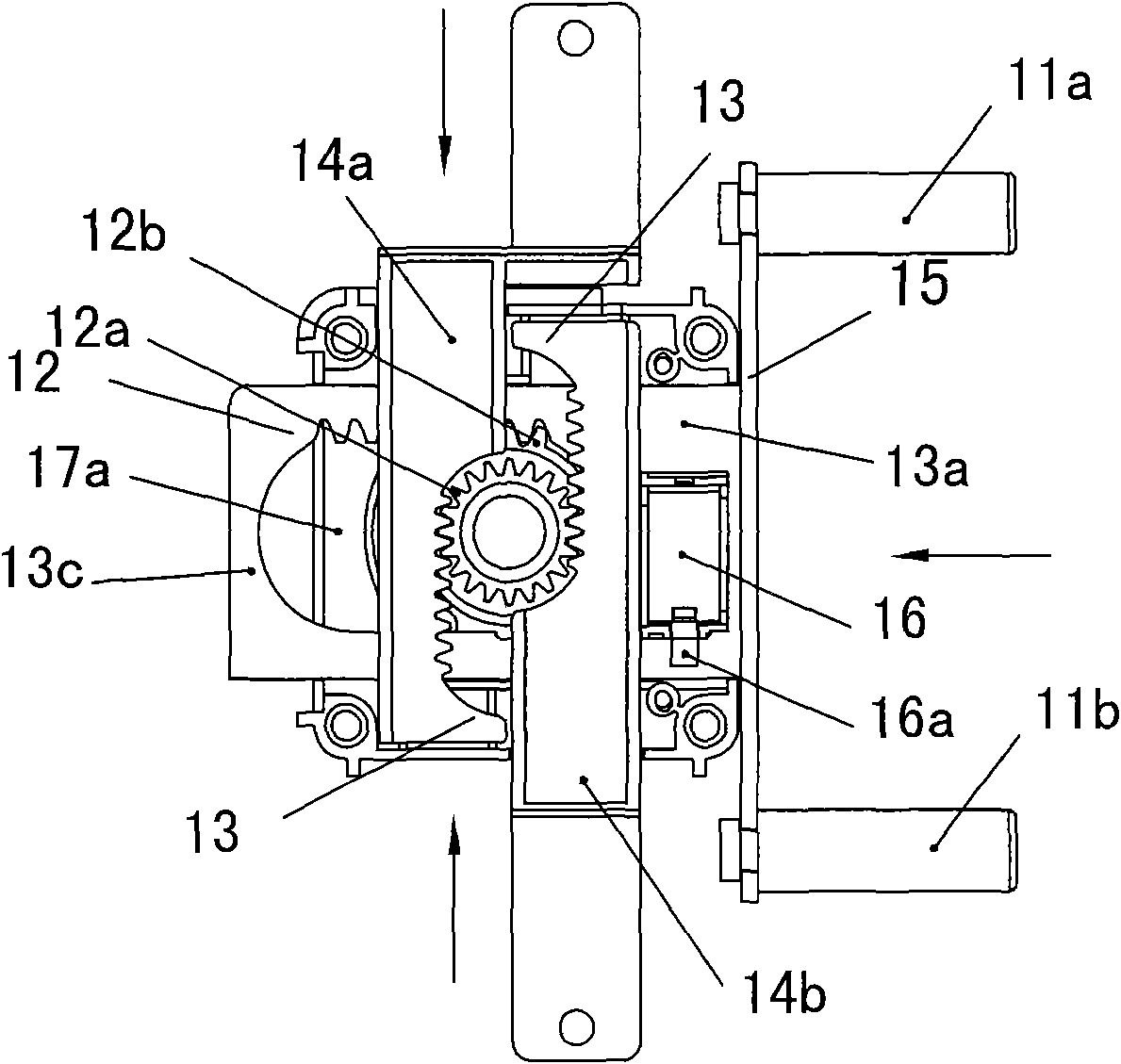
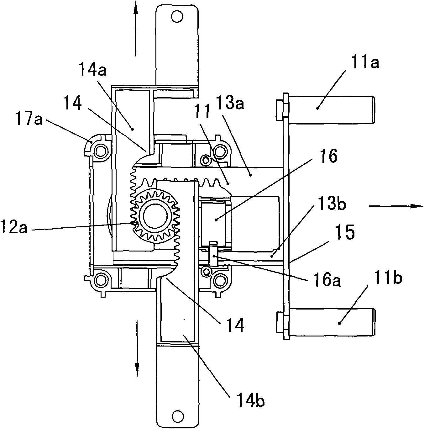
[0032] Such as Figure 1~5 As shown, a three-way locking device of the present invention includes a box body, horizontal lock bolts 11a and 11b, vertical lock bolts 18a and 18b, and a lock bolt movement mechanism located in the box body; the lock bolt movement mechanism is a gear transmission mechanism, The gear transmission mechanism includes a vertical transmission part, a horizontal transmission part, a lock cylinder hinged in the box body and an upper gear 12a and a lower gear 12b installed on the lock cylinder. Both the horizontal transmission part and the vertical transmission part have an inner section with a rack The structure is used to mesh with the upper gear 12a and the lower gear 12b respectively, and they also all have an outer section extending out of the box body for connecting respectively the horizontal lock bolts 11a, 11b and the vertical lock bolts 18a, 18b, and the lock cylinder rotates to drive The upper and lower gears rotate, and the upper and lower gea...


PUM


Abstract

The invention discloses a three-way locking device which comprises a box body, a transverse lock bolt, a vertical lock bolt and a lock bolt movement mechanism arranged in the box body, wherein the lock bolt movement mechanism is a gear transmission mechanism which comprises a vertical transmission piece, a transverse transmission piece, a lock cylinder hinged in the box body as well as an upper gear and a lower gear which are arranged on the lock cylinder; both the transverse transmission piece and the vertical transmission piece are respectively provided with an inner section which has a rack structure and is respectively used for engaging the upper gear and the lower gear, and the transverse transmission piece and the vertical transmission piece are also respectively provided with an outer section which extends out of the box body and is used for respectively connecting with the transverse lock bolt and the vertical lock bolt; the lock cylinder rotates to drive the two gears to rotate; and the upper gear and the lower gear respectively drive the transverse transmission piece and the vertical transmission piece to do linear motion to ensure that the transverse lock bolt and the vertical lock bolt extend outwards or contract inwards. The invention also discloses a three-way locking bolt electric control semi-automatic lock adopting an electric control operation of the three-way locking device. The invention has the advantages of simple structure, low manufacturing cost, simpler matching relation of all parts and strong working reliability.

Description

technical field [0001] The present invention relates to a lock, in particular to a three-way locking device, and also relates to a three-way locking electronically controlled semi-automatic lock in which the above-mentioned three-way locking device adopts electric control operation. Background technique [0002] At present, electric locks have been widely used in people's lives. It generally includes an electronic control module and a mechanical locking device. The electronic control module realizes locking and unlocking of the electric lock by controlling the action of the locking device. The locking devices of existing electric locks are divided into full-electric locking devices and semi-electric locking devices. In the semi-electric locking device, the electronic control module first releases the lock bolt limit mechanism, and then the lock bolt is opened by the manual handle outside the door, so as to realize unlocking. Although the all-electric locking device can real...

Claims


Application Information

Patent Timeline
Patent Type & Authority Applications(China)
IPC IPC(8): E05B47/02E05B63/14
Inventor 任剑波钟长林
Owner GUANGZHOU GUUB TECH
Learn More