Adhesive structured pigtail type detector

A technology of detectors and detector chips, applied in the field of detectors, can solve problems such as increasing processing costs and affecting the integrity and consistency of product surface shapes, so as to avoid glue bursting, ensure integrity and consistency, and reliability Good results

Active Publication Date: 2011-02-16
SUSR COMM TECH
View PDF9 Cites 2 Cited by
  • Summary
  • Abstract
  • Description
  • Claims
  • Application Information

AI Technical Summary

Problems solved by technology

The disadvantage of this method is: small hole processing not only increases the processing cost of the product, but also affects the integrity and consistency of the product surface shape

Method used


Image

  • Adhesive structured pigtail type detector
  • Adhesive structured pigtail type detector
  • Adhesive structured pigtail type detector

Examples


Embodiment Construction

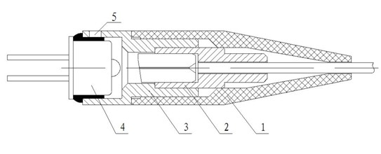
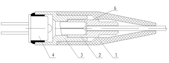
[0011] An adhesive structure pigtail type detector, such as figure 2 As shown, it includes a rubber sheath 1 , an optical fiber assembly 2 , a metal shell 3 , a detector chip 4 and a platform 6 .

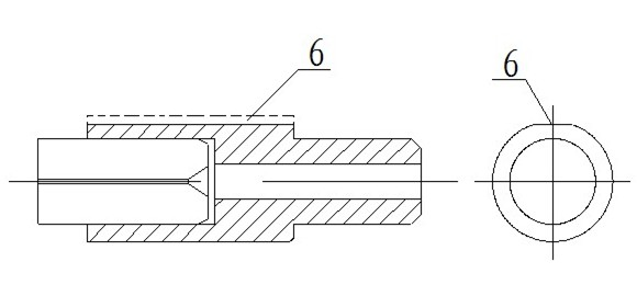
[0012] like image 3 As shown, when the optical fiber assembly 2 is processed, a platform 6 is processed on its outer circle with a depth of 0.01 to 0.5 mm, and the best effect is when the depth is 0.1 mm. The gap between the optical fiber assembly 2 and the metal shell 3 is too small, so that dust and impurities can easily enter the inside of the device, and the ventilation effect of the device is not bad because the gap between the optical fiber assembly 2 and the metal shell 3 is too small. The number of platforms is not limited to one, but can also be two or more. The number and depth of platforms can be matched, and the most appropriate number of platforms and depth of platforms can be selected on the basis of comprehensive consideration of processing costs and product perfor...


PUM


Abstract

The invention discloses an adhesive structured pigtail type detector which comprises a rubber sheath, an optical fiber assembly, a metal shell and a detector chip, wherein the optical fiber assembly and the metal shell are connected; the optical fiber assembly and the detector chip are coupled; the detector chip and the metal shell are bonded by glue; and an outer circle of the optical fiber assembly is provided with a platform. The adhesive pigtailed detector has the advantages that a gap between the optical fiber assembly and the inner part of the metal shell is reserved by changing the structure of the optical fiber assembly, which is beneficial to the exhausting of gas generated in the curing of the glue so as to prevent the glue from bubble burst; the index of the detector is ensured to reach the standard all the time, be free from the influenced of the processing course; the production cost is reduced; and the product reliability is better.

Description

technical field [0001] The invention relates to a detector for receiving CATV signals, in particular to a pigtail type detector with an adhesive structure. Background technique [0002] The working principle of the existing detector for receiving CATV signals is that the 1550nm wavelength optical signal is transmitted through the optical fiber component, received by the detector chip, and then converted into an electrical signal to be connected to the TV. Its structure is figure 1 As shown, it includes a rubber sheath 1 , an optical fiber assembly 2 , a metal shell 3 , a detector chip 4 and a small hole 5 . Among them: after the optical fiber assembly 2 and the metal shell 3 are connected by adhesive bonding, they are coupled with the detector chip 4. After the responsivity index meets the requirements, the detector chip 4 and the metal shell 3 are bonded with glue, and then the glue is glued at high temperature. cured. Because the internal space of the device is closed w...

Claims


Application Information

Patent Timeline
Patent Type & Authority Applications(China)
IPC IPC(8): G01D5/26G01D11/24
Inventor 张树刚于浩
Owner SUSR COMM TECH
Why Eureka
Try Eureka