Piezoelectric fan and cooling device using piezoelectric fan

A piezoelectric fan, heat sink technology, applied in piezoelectric effect/electrostrictive or magnetostrictive motors, piezoelectric/electrostrictive/magnetostrictive devices, generators/motors, etc., and can solve characteristic changes , Affect the durability, reliability, noise and other issues of the piezoelectric fan, and achieve the effect of efficient cooling, preventing blade twisting, and avoiding contact

Inactive Publication Date: 2011-02-16
MURATA MFG CO LTD
View PDF9 Cites 4 Cited by
  • Summary
  • Abstract
  • Description
  • Claims
  • Application Information

AI Technical Summary

Problems solved by technology

When unexpected vibration such as torsional vibration occurs, the durability and reliability of the piezoelectric fan will be affected, and the contact between the blade and the heat sink will not only cause noise, but also cause changes in characteristics due to damage, wear, etc.

Method used


Image

  • Piezoelectric fan and cooling device using piezoelectric fan
  • Piezoelectric fan and cooling device using piezoelectric fan
  • Piezoelectric fan and cooling device using piezoelectric fan

Examples


Embodiment approach 1

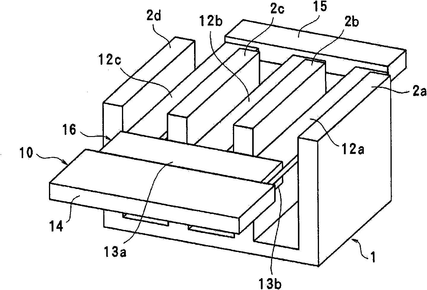
[0030] Figure 1 to Figure 5 This is an example showing an air cooling device using Embodiment 1 of the piezoelectric fan according to the present invention as the heat sink 1 . The heat sink 1 has a plurality (here, four) of heat sinks 2 a to 2 d arranged side by side with intervals therebetween. Cooling device 1 such as Figure 4 and Figure 5 As shown, it is mounted on the upper surface of a heating element (CPU, etc.) 4 mounted on a circuit board 3 in a thermally bonded state. Therefore, the heat generated by the heating element 4 is transferred to the heat sink 1, thereby heating the air between the heat sinks 2a to 2d.

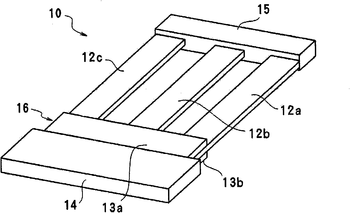
[0031] The piezoelectric fan 10 of this embodiment is as figure 2 and image 3As shown, there is a metal plate 11 with high spring elasticity such as a stainless steel plate. On one end side in the longitudinal direction of the metal plate 11, a substrate portion 11a continuous in the width direction is formed, and a plurality (here, 3) of the sam...

Embodiment approach 2

[0036] Image 6 Embodiment 2 of the piezoelectric fan according to the present invention is shown. In this embodiment, the same reference numerals are used for the same parts as those in Embodiment 1, and repeated descriptions are omitted. In the piezoelectric fan 10a of the present embodiment, a coupling portion 15a integrally formed with the blades 12a to 12c is formed at the free end portion in the longitudinal direction of the blades 12a to 12c. An extension part 11b extending to the opposite side of the blade extending direction and to which the piezoelectric elements 13a, 13b are not bonded is integrally formed with the base plate part 11a. This extension part 11b is held by the support body which is not shown in figure. In this case, since the substrate portion 11a, the blades 12a to 12c, and the connection portion 15a are formed of a single metal plate, the piezoelectric fan 10a can be configured with a small number of parts and at low cost. Furthermore, since the e...

Embodiment approach 3

[0038] Figure 7 3 shows Embodiment 3 in which the piezoelectric fan according to the present invention is used as an air cooling device of the heat sink 1a. In this embodiment, the same reference numerals are used for the same parts as those in Embodiment 1, and repeated descriptions are omitted. In the piezoelectric fan 10b of this embodiment, the intermediate parts in the longitudinal direction of the blades 12a to 12c are connected to each other by the connecting part 17, and the heat dissipation fins 2b and 2c of the heat sink 1a corresponding to the connecting part 17 are connected to each other in the longitudinal direction. Groove portions 2e, 2f are formed in the upper middle portion. Therefore, when the blades 12a to 12c are displaced in the thickness direction, the coupling portion 17 can freely move up and down in the grooves 2e and 2f, and can prevent these blades 12a to 12c from coming into contact with the fins 2b and 2c.

[0039] In this embodiment, the free ...


PUM


Abstract

Disclosed is a highly durable, highly reliable piezoelectric fan in which twisting of the blades is inhibited when a plurality of blades are displaced by bending between a plurality of heat-radiating fins of a heat sink. A piezoelectric fan (10) comprises a piezoelectric vibrator (16) which undergoes bending vibration when a voltage is applied thereto, and a plurality of parallel blades (12a) to (12c) joined to or integral with the piezoelectric vibrator, and the blades are inserted between heat-radiating fins (2a) to (2d) of a heat sink (1) in such a way as to be able to be displaced by bending in a direction parallel to the side of the heat-radiating fins. A joint (15) for joining the blades together is provided at a free end in the longitudinal direction of the blades (12a) to (12c). When the blades are vibrated by the piezoelectric vibrator and warm air is discharged between the heat-radiating fins, the joint (15) inhibits the twisting of the blades.

Description

technical field [0001] The present invention relates to a piezoelectric fan that discharges hot air between heat sink fins of a heat sink by bending and vibrating a piezoelectric vibrator to greatly bend and displace a blade connected thereto. Background technique [0002] In recent years, as portable electronic devices, along with miniaturization and high-density mounting of components, heat radiation treatment of heat generated inside electronic devices has become a problem. As a device for efficiently air-cooling such electronic devices, an air-cooling device using a piezoelectric fan has been proposed. [0003] Patent Document 1 discloses a heat sink in which a plurality of movable fins are attached to a rotating shaft, each movable fin is inserted between a plurality of fins arranged side by side at intervals for a heat generating part of a heat generating body, and Make the rotating shaft rotate continuously or swing within a predetermined angle range, so as to send c...

Claims


Application Information

Patent Timeline
Patent Type & Authority Applications(China)
IPC IPC(8): H01L23/36H02N2/00F04D33/00
CPCF04D33/00H01L41/094H01L23/467H01L2924/0002H10N30/2042H01L2924/00
Inventor 和田宽昭神谷岳
Owner MURATA MFG CO LTD
Why Eureka
Try Eureka