Electrical tester setup and calibration device

A test device, electronic test technology, applied in the direction of measuring devices, manufacturing measuring instruments, instruments, etc.

Inactive Publication Date: 2011-02-16
ELECTRO SCI IND INC
View PDF4 Cites 2 Cited by
  • Summary
  • Abstract
  • Description
  • Claims
  • Application Information

AI Technical Summary

Problems solved by technology

This method does not test the measurement card in isolation, but includes noise and voltage level errors from the source

Method used


Image

  • Electrical tester setup and calibration device
  • Electrical tester setup and calibration device
  • Electrical tester setup and calibration device

Examples


Embodiment Construction

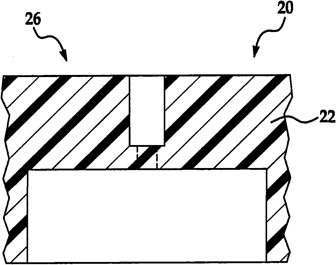
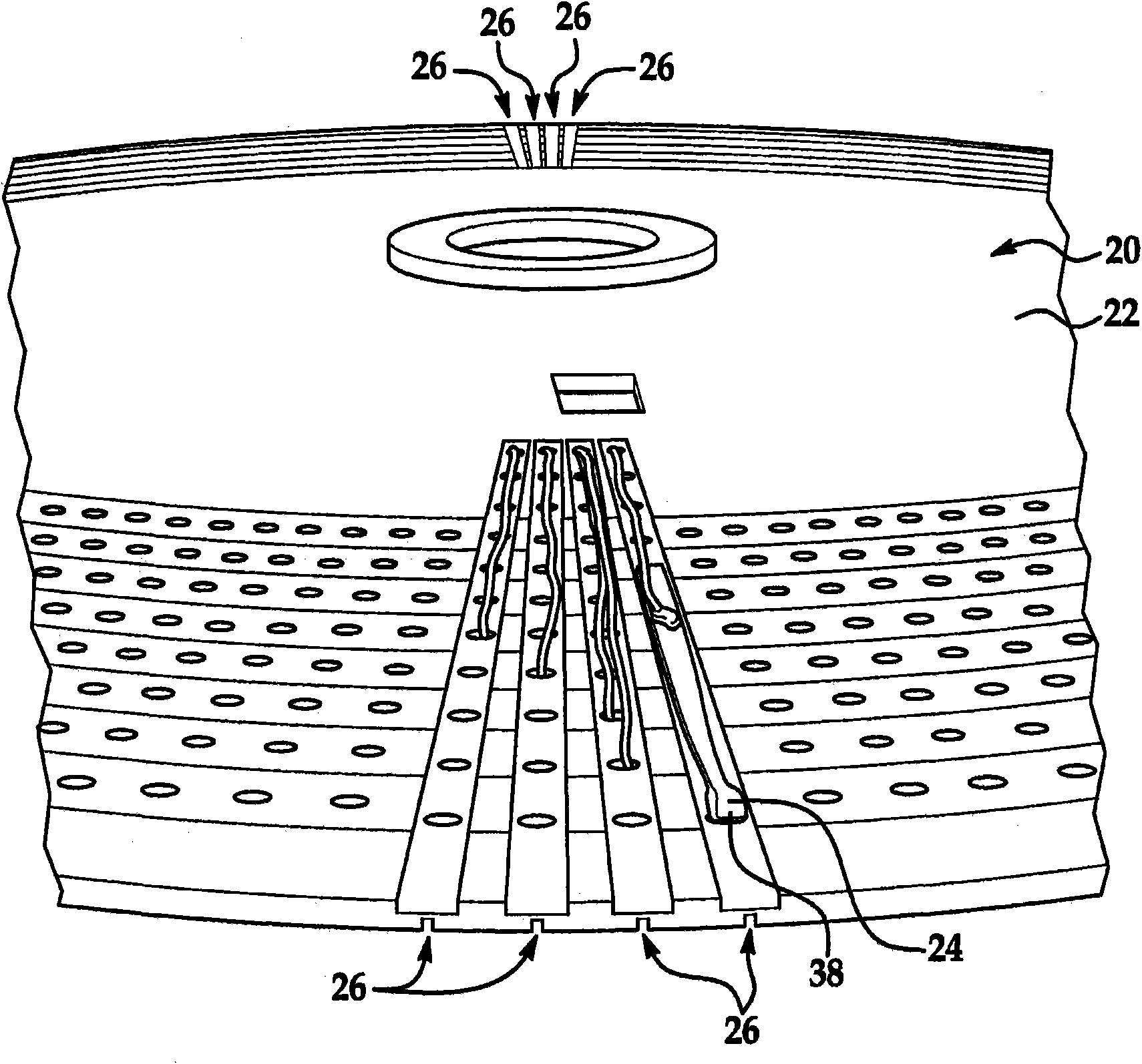
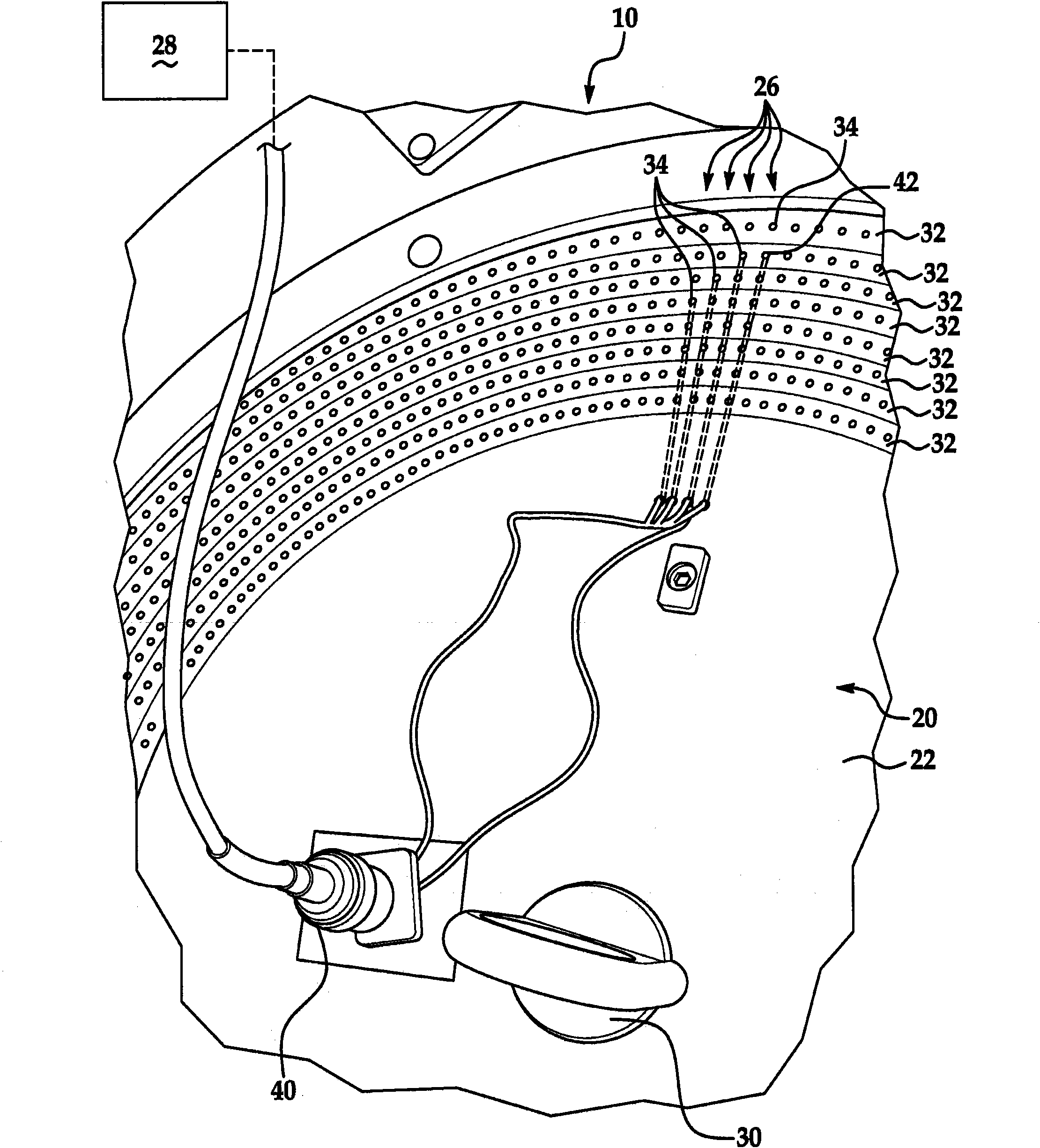
[0017] see briefly Figure 6 and Figure 7 , the electronic testing machine 10 has at least one upper contact 14 and at least one lower contact 16 of the test module 12 . Each test module 12 is positionable on angularly spaced radial lines extending from an associated central axis and has a plurality of contact pairs 14, 16 for testing electronic components. The production test plate or disc 50 includes a plurality of pockets 52 . Each pocket 52 can carry an electronic component 54 to the test location 26 for electrical insertion between the upper contacts 14 and the lower contacts 16 of the test module 12 of the electronic testing machine 10 to perform a test on the electronic component 54. or more than one test. The test board 50 is rotated about the central axis to transfer the electronic assemblies 54 to and from the test locations 26 associated with the corresponding upper contacts 14 and lower contacts 16 of the different test modules 12 . It should be understood tha...


PUM


Abstract

An electronic testing machine includes a plurality of test modules, each of which has a plurality of contact pairs for testing electronic components. An apparatus and process for electrical test setup and calibration of the electronic testing machine includes a plate having at least one contact per track movable between test positions to electrically insert a test device selectively between any one contact pair. A control program can perform at least one test function through the plate.

Description

technical field [0001] The present invention relates to an apparatus and method for the setup and calibration of an electronic testing machine comprising a plurality of test modules, each test module having a plurality of contacts for testing electronic components. Background technique [0002] The setup and calibration of electronic test machines is known to be a difficult and time consuming task. Typically, the setup and calibration process includes one or more of the following tasks: contact alignment and verification, voltage source calibration and verification, current source calibration and verification, insulation resistance (IR) leakage measurement calibration and verification test, and source and measure compensation. [0003] Alignment verification is currently known to be performed using software alignment by an upper contact alignment tool that uses a row of parts and contact inspection in a test board to automate alignment measurements, but this Tool does not ...

Claims


Application Information

Patent Timeline
IPC IPC(8): G01R19/145G01R31/00
CPCG01R35/005G01R31/31908G01R31/2886G01R3/00
Inventor 斯潘塞·B·巴雷特布兰登·J·麦柯里肯尼思·V·阿尔蒙特
Owner ELECTRO SCI IND INC
Why Eureka
Try Eureka