Pressure-actuated member, in particular paint pressure controller or coating agent valve

A technology of pressure regulator and pressure regulation, which is applied in the direction of fluid pressure control, control/regulation system, auxiliary non-electric fluid pressure control, etc., and can solve problems such as the separate sealing device of the supply valve

Active Publication Date: 2011-02-16
DUERR SYST GMBH
View PDF1 Cites 5 Cited by
  • Summary
  • Abstract
  • Description
  • Claims
  • Application Information

AI Technical Summary

Problems solved by technology

[0006] Another disadvantage of the aforementioned known paint pressure re

Method used


Image

  • Pressure-actuated member, in particular paint pressure controller or coating agent valve
  • Pressure-actuated member, in particular paint pressure controller or coating agent valve
  • Pressure-actuated member, in particular paint pressure controller or coating agent valve

Examples


Embodiment Construction

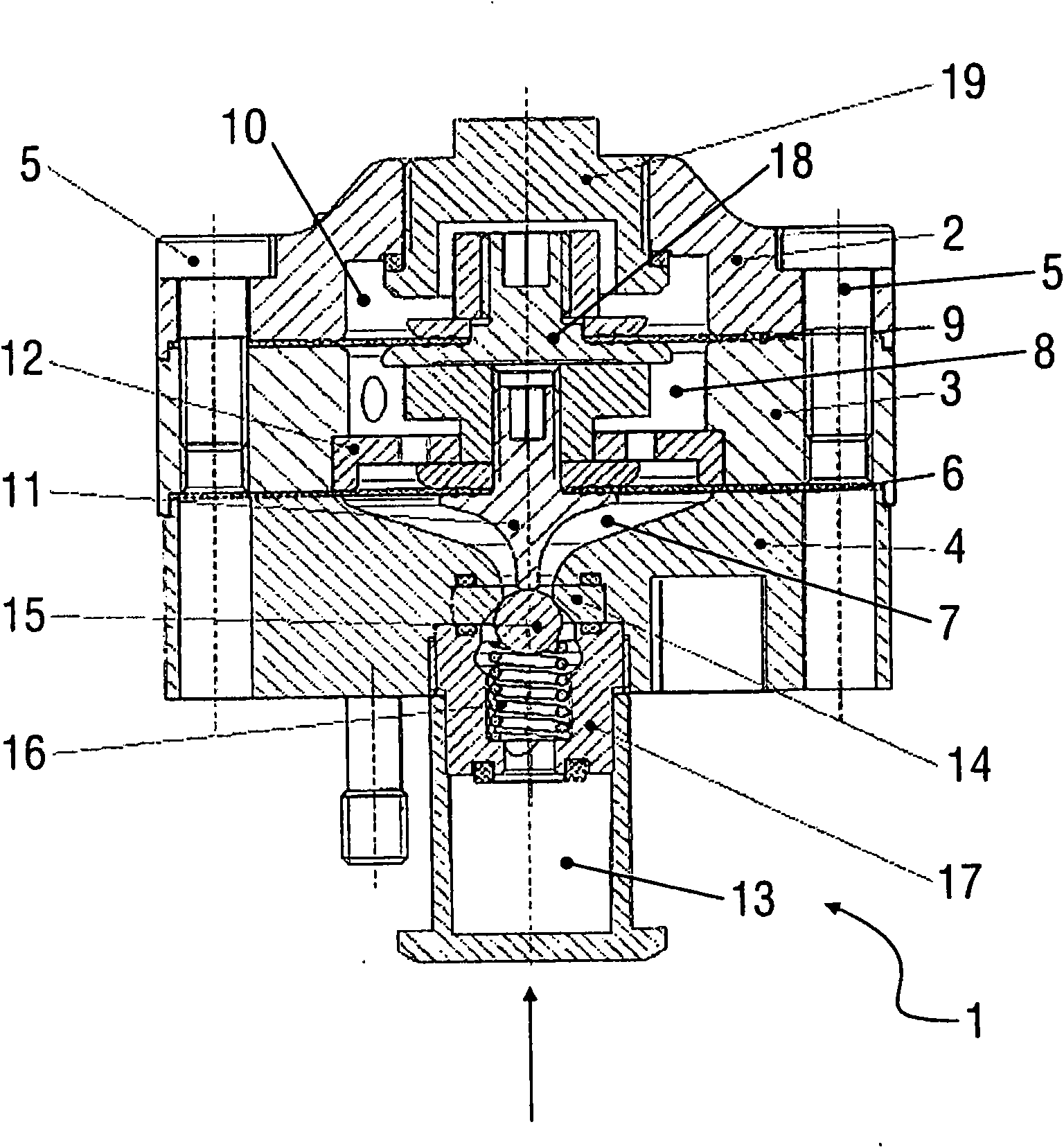
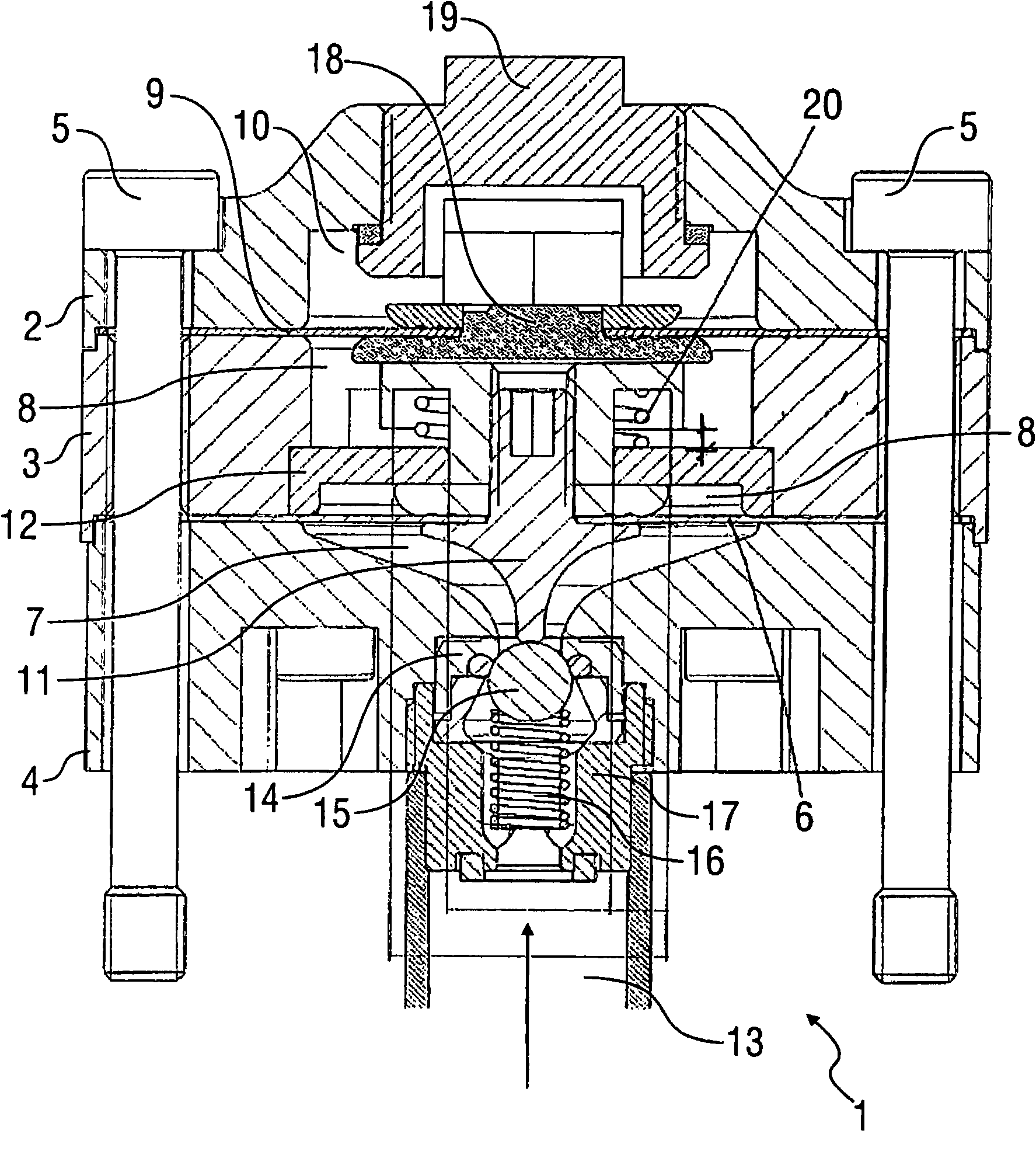
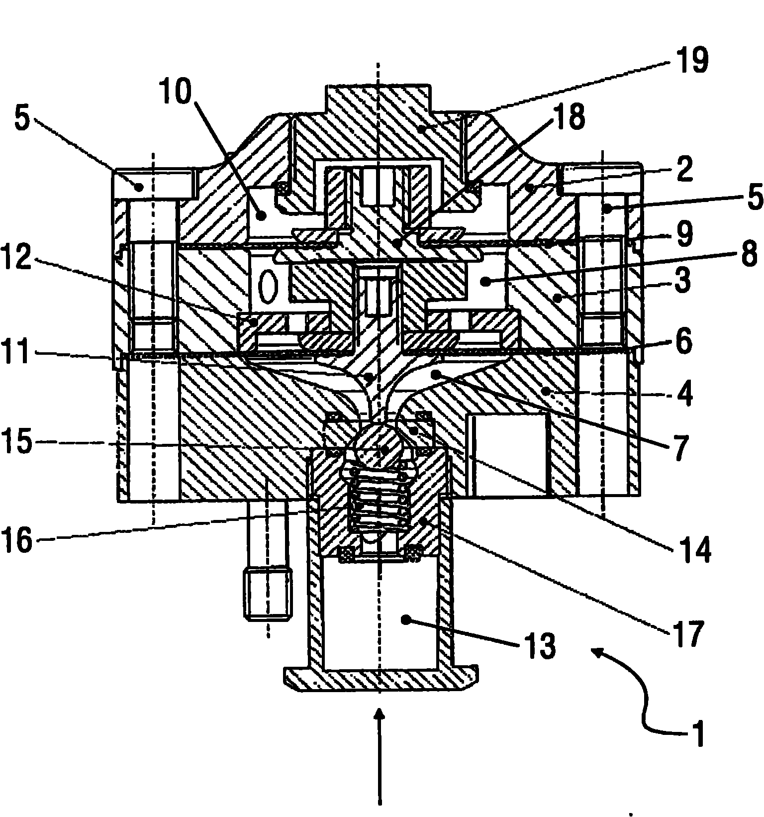
[0036] figure 1 A paint pressure regulator 1 according to the invention is shown for regulating the pressure of a paint medium in a paint system.

[0037] The paint pressure regulator 1 largely corresponds to the conventional paint pressure regulator described, for example, in patent application EP1376289A1, so that the contents of said patent application with regard to the structure and the mode of function of the paint pressure regulator 1 All are included in this manual.

[0038] Paint pressure regulator 1 has three housing parts 2 , 3 , 4 placed one above the other, which are fixedly connected to one another by screws 5 .

[0039]Between the housing part 3 and the housing part 4 there is a membrane 6 made of ceramic fiber composite material, wherein the membrane 6 separates the paint chamber 7 from the control air chamber 8 .

[0040] Between the housing part 2 and the housing part 3 there is a further diaphragm 9 which is also made of ceramic fiber composite material an...


PUM


Abstract

The invention relates to a pressure-actuated member (1), in particular a paint pressure controller or a coating agent valve, for influencing a mean coating agent pressure of a coating agent to be applied in a painting system, comprising a component (6, 14), which is subjected directly to the coating agent during operation and is mobile and/or can be deformed to influence the pressure. It is proposed that the component (6, 14) subjected to the coating agent at least partially comprises a ceramic material in order to achieve a longer service life.

Description

technical field [0001] The invention relates to a pressure regulating device, in particular a paint pressure regulator or a coating medium valve, for influencing the coating medium pressure of the coating medium to be applied in a painting installation. Background technique [0002] Such a paint pressure regulator is known, for example, from EP 1376289 A1 and is used to regulate the coating medium pressure in painting installations. The known paint pressure regulator has a paint chamber with a paint inlet and a paint outlet, wherein a spring-loaded feed valve is arranged in the paint inlet, which closes off all paint in the rest state. The above paint inlet. Furthermore, the known paint pressure regulator has a control air chamber which is directly adjacent to the paint chamber and is separated from it by a flexible membrane. The control air chamber is loaded with adjustable control air pressure during work, and the control air pressure acts on the diaphragm between the co...

Claims


Application Information

Patent Timeline
IPC IPC(8): G05D16/18
CPCG05D16/0633G05D16/0672G05D16/185B05B12/088Y10T29/49405Y10T29/49407Y10T137/7837F16K27/02
Inventor T·布克M·博伊曼R·梅尔歇尔
Owner DUERR SYST GMBH
Why Eureka
Try Eureka