Circuitry for inductive power transfer

A power transmission and circuit technology, applied in the direction of circuits, circuit devices, battery circuit devices, etc.

Active Publication Date: 2011-02-16
PHILIPS IP VENTURES BV
View PDF3 Cites 42 Cited by
  • Summary
  • Abstract
  • Description
  • Claims
  • Application Information

AI Technical Summary

Problems solved by technology

However, a number of disadvantages regarding cost, performance and complexity have been recognized ...

Method used


Image

  • Circuitry for inductive power transfer
  • Circuitry for inductive power transfer
  • Circuitry for inductive power transfer

Examples


Embodiment Construction

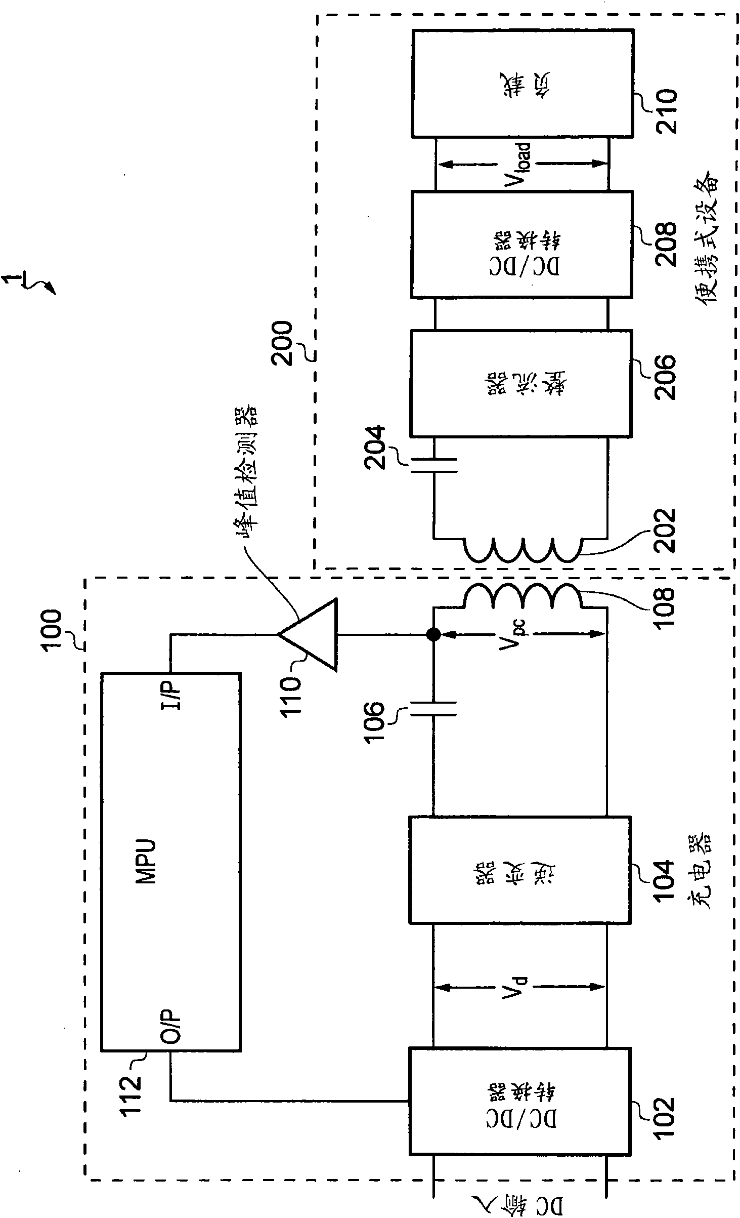
[0069] In order to better understand embodiments of the invention, reference will first be made to an exemplary inductive power transfer system 1 which does not directly embody the invention but is useful for understanding embodiments of the invention.

[0070] figure 1 is a schematic diagram of System 1. The system 1 comprises a primary unit (charger) 100 and a secondary unit (in this case a portable device) 200 .

[0071] The primary unit 100 includes a DC / DC converter 102 , an inverter 104 , a capacitor (or capacitance) 106 , a primary coil 108 , a buffer 110 and a microprocessor unit (MPU) 112 . The secondary unit 200 includes a secondary coil 202 , a capacitor (or capacitance) 204 , a rectifier 206 , a DC / DC converter 208 and a load 210 . Buffer 110 may be considered a peak detector and may be used to measure the peak voltage across primary coil 108 .

[0072] The primary unit 100 is configured to generate an electromagnetic field, and this field may be induced in the ...


PUM


Abstract

Circuitry for use in a primary unit of an inductive power transfer system to generate an electromagnetic field so as to transfer power wirelessly by electromagnetic induction to one or more secondary units of the system, the or each secondary unit being separable from the primary unit, the circuitry comprising: a plurality of drivable portions, each portion comprising a primary coil or a dummy coil; driving means operable to supply both or at least two of said portions with drive signals so as to cause those driven portions that have a said primary coil to generate said electromagnetic field; and control means operable, in dependence upon a feedback signal indicative of a characteristic of the primary or dummy coil of one or more of the driven portions, to control the circuitry so as to tend to regulate said feedback signal, wherein the circuitry is configured so that; those portions that are driven are connected together in parallel and have a tuned resonant response; and said control tends to regulate such a characteristic of each of said driven coils.

Description

technical field [0001] The present invention relates to circuits for use in inductive power transfer systems, eg for powering portable electrical or electronic equipment. [0002] An inductive power transfer system suitable for powering portable devices can consist of two parts: [0003] • A primary unit having at least one primary coil through which it drives an alternating current, thereby creating a time-varying magnetic flux. [0004] • A secondary unit, separable from the primary unit, with a secondary coil. Background technique [0005] When the secondary coil is placed in close proximity to the time varying flux created by the primary coil, this varying flux induces an alternating current in the secondary coil and thus power can be transferred inductively from the primary unit to the secondary unit. [0006] Generally, the secondary unit provides the transferred power to an external load, and the secondary unit may be hosted in or contained by a host object (seconda...

Claims


Application Information

Patent Timeline
IPC IPC(8): H02J5/00
CPCH02J7/025H02J5/005H02J7/045Y02T90/12Y02T10/7072Y02T90/14B60L53/124B60L53/126B60L53/122Y02T10/70H02J7/04H02J50/402H02J50/80H02J7/00714H02J50/90H02J7/007182H02J50/12H02J50/15H02J50/30H02J50/40H02J50/60B60L53/12B60L53/30H01F38/14H02J7/0029Y04S30/12Y02T90/167
Inventor W·H·莱门斯D·M·普利J·德克勒克
Owner PHILIPS IP VENTURES BV
Why Eureka
Try Eureka