Eureka AIR delivers breakthrough ideas for toughest innovation challenges, trusted by R&D personnel around the world.

Universal orthogonal coupler

A coupling and universal technology, which is applied in the direction of couplings, elastic couplings, wind power generation, etc., can solve the problems of short distance between shaft ends, large compensation amount, and inability to compensate the runout between shafts, etc., and achieve the distance between shaft ends The effect of small size, large amount of compensation and high precision

Inactive Publication Date: 2011-02-23
苏州高新区禾云设备设计事务所
View PDF4 Cites 3 Cited by
  • Summary
  • Abstract
  • Description
  • Claims
  • Application Information

AI Technical Summary

Problems solved by technology

[0005] ①Oldham coupling: It can compensate the runout between shafts, and the compensation amount is large, but the accuracy is poor and the angle between shafts cannot be compensated
But the connection distance between the shaft ends is long
[0008] ④Plum blossom elastic rubber coupling: It can compensate the angle between the shafts and the radial runout, but the compensation amount is small and the accuracy is poor
[0009] ⑤Plunger elastic rubber coupling: It can compensate the angle between the shafts and the radial runout, but the compensation amount is small and the accuracy is poor
[0010] ⑥Single-section ten-byte coupling: it can compensate the angle between the shafts, the compensation amount is large, and there is no backlash interval, but it cannot compensate the run-out between the shafts
And the amount of compensation required is large, and the distance between the shaft ends is short and the backlash gap is small.
Therefore, the existing movable couplings still cannot fully meet the needs of practical use technically.

Method used


Image

  • Universal orthogonal coupler
  • Universal orthogonal coupler

Examples


Embodiment Construction

[0027] The technical implementation process of the present invention will be further described below in conjunction with the accompanying drawings and embodiments.

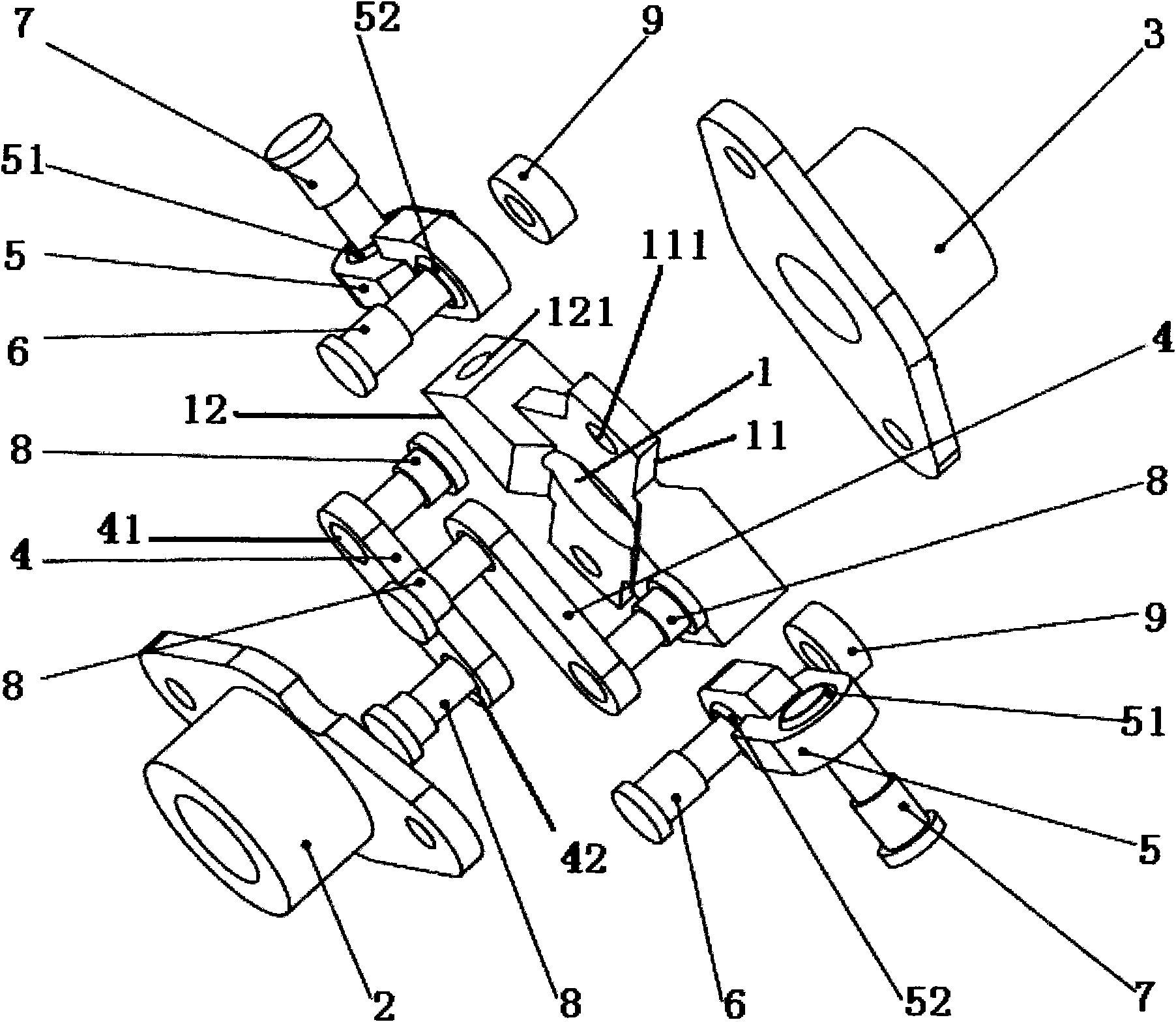
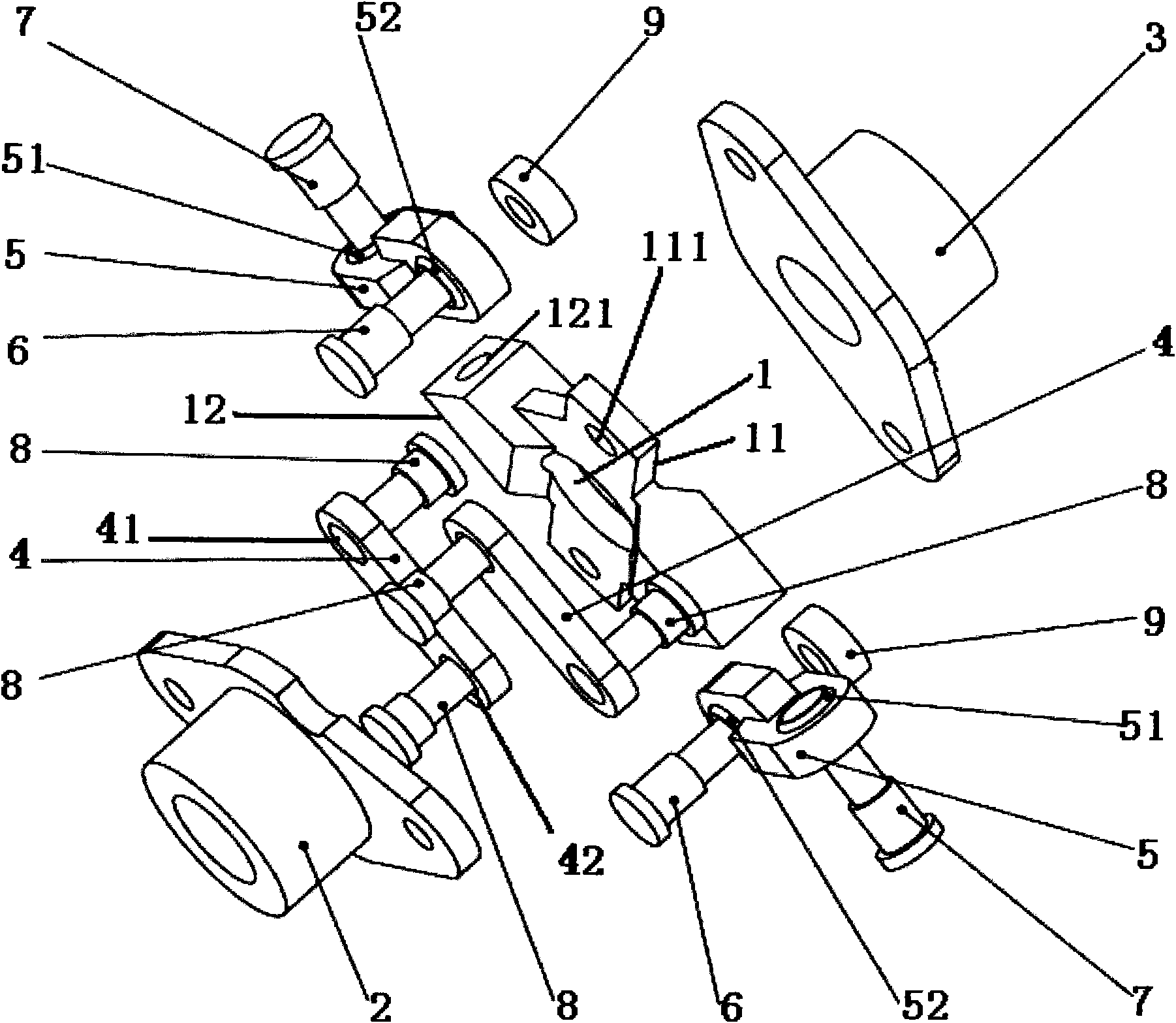
[0028] see figure 1 As shown, a universal orthogonal shaft coupling includes an intermediate bracket 1, a fixed shaft seat 2 and a universal shaft seat 3, and the fixed and universal shaft seats 2 and 3 are provided with pin shafts at both ends There is a structure with a shaft hole in the middle of the hole; the middle support 1 is a symmetrical cross structure in pairs, and the first symmetrical support 11 of the cross structure is a structure with a fixed pin shaft hole 111 on the plane. The second symmetrical support 12 is a structure in which the middle pin hole 121 is opened on the end face; the fixed shaft seat 2 is fixed on the first symmetrical support 11 through a parallel connecting arm 4; The connecting arm 5 is movably connected to the second symmetrical support 12 .

[0029] Further, a first fixing...


PUM


Abstract

The invention discloses a universal orthogonal coupler. The universal orthogonal coupler comprises a middle bracket, a fixed shaft seat and a universal shaft seat, wherein the fixed shaft seat and the universal shaft seat have a structure on which a pin shaft hole is formed at two ends respectively and a shaft hole is formed in the middle; the middle bracket has a cross structure in which brackets are symmetrically pairwise; the first pair of symmetrical brackets of the cross structure has a structure on which a fixed pin shaft hole is formed on the plane; the second pair of symmetrical brackets of the cross structure has a structure on which a middle pin shaft hole is formed on the end face; the fixed shaft seat is fixed on the first symmetrical brackets through a parallel connecting arm; and the universal shaft seat is moveably connected to the second symmetrical brackets through an orthogonal connecting arm. The coupler of the invention can compensate for interaxial included angle, radial bounce and floating change of shaft end distance. The shaft end distance is small; the compensation dosage is large; and the return difference distance is small.

Description

technical field [0001] The invention relates to a shaft coupling, in particular to a universal orthogonal shaft coupling used for power connection between a rotating main shaft driven by wind and a generator in wind power generation. Background technique [0002] There are many types of couplings, which can be divided into: [0003] (1) Fixed coupling. It is mainly used in places where the two shafts require strict alignment and no relative displacement occurs during work. The structure is generally simple and easy to manufacture, and the instantaneous speed of the two shafts is the same. There are mainly flange couplings, sleeve couplings, and clamps. Shell couplings, etc. [0004] (2) Movable coupling. It is mainly used in places where the two shafts are deflected or there is relative displacement during work. According to the method of compensating displacement, it can be divided into rigid movable coupling and elastic movable coupling. There are mainly the following ...

Claims


Application Information

Patent Timeline
IPC IPC(8): F16D3/44F03D11/00F16D3/26
CPCY02E10/722
Inventor 张晓鹤
Owner 苏州高新区禾云设备设计事务所
Why Eureka
Eureka Blog
Learn More