Glass melting furnace

A glass melting furnace and melter technology, applied in glass furnace equipment, glass production, glass manufacturing equipment, etc., can solve the problem of expensive materials

Active Publication Date: 2014-02-26
AGC GLASS EUROPE
View PDF5 Cites 0 Cited by
  • Summary
  • Abstract
  • Description
  • Claims
  • Application Information

AI Technical Summary

Problems solved by technology

In the case of oxy-fuel combustion furnaces, it is more precisely necessary to resort to materials such as alumina, AZS or s

Method used


Image

  • Glass melting furnace
  • Glass melting furnace
  • Glass melting furnace

Examples


Embodiment Construction

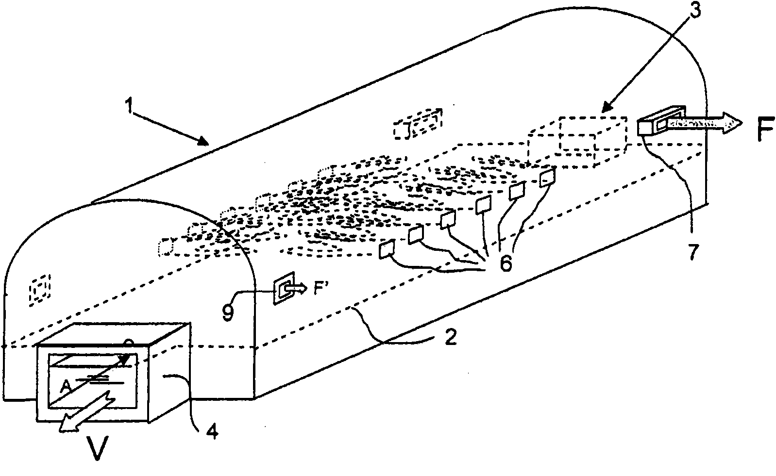
[0088] figure 1 The furnaces shown in are of the type used in mass glass production, such as those used for feeding flat glass production units using suspension glass technology. This type of furnace can continuously produce glass in quantities up to 1000 tons / day. To achieve these properties, the furnace must have a power of up to 60MV.

[0089] The furnace 1 comprises a pool arranged in a closed chamber. The assembly is constructed of refractory materials that are resistant to high temperatures, corrosion by exhaust gases, and corrosion by molten materials. The height of the molten bath in the pool is indicated by dashed line 2.

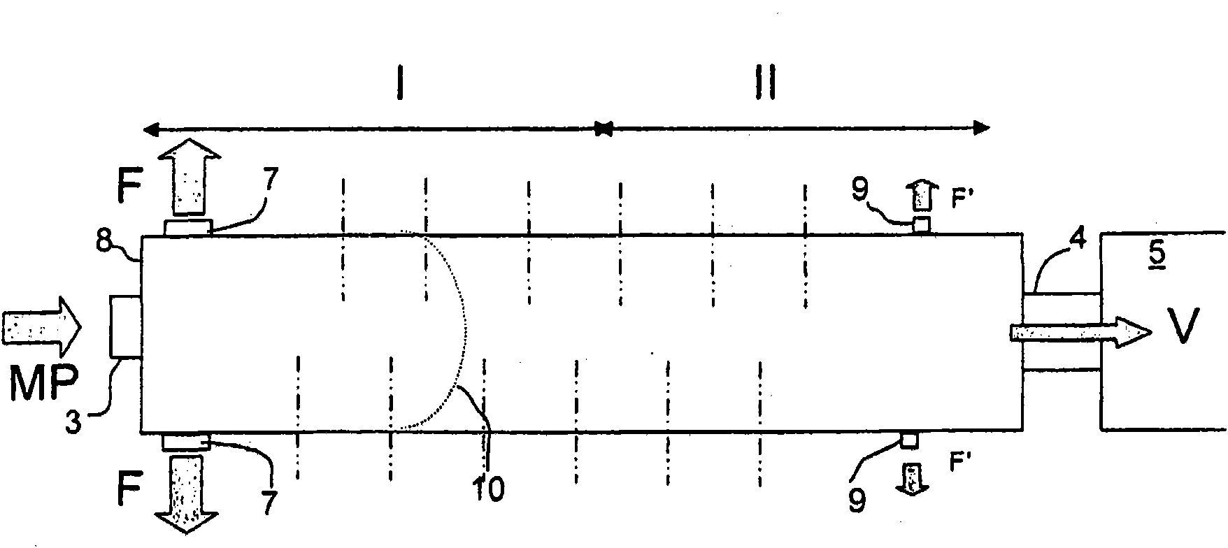
[0090] The furnace is fed raw material at one end thereof. The opening through which the raw material is charged into the furnace is indicated at 3 . In fact, in order to facilitate distribution on the surface of the molten bath, multiple furnace loading points are usually set. The output of the molten glass, indicated by the arrow V, takes p...


PUM


Abstract

The present invention relates to a glass meting furnace comprising a channel-shaped melting tank, the batch materials being introduced at an upstream end, the molten glass being recovered at the downstream end, said furnace being heated by means of burners, in which the combustion energy is produced by oxy-fuel combustion in respect of at least 65% thereof, the burners being distributed on the walls along the length of the furnace, in which flue gas discharge is mostly localized close to the upstream end near the openings through which the batch materials are introduced, the rest of the flue gas being removed close to the downstream part so as to maintain dynamic sealing with respect to the surrounding atmosphere.

Description

technical field [0001] The present invention relates to glass melting furnaces in which the melting energy is substantially generated by burners that are alimneter and fed oxygen or oxygen-enriched gas. These furnaces are generally defined as "oxy-combustion" furnaces. Background technique [0002] The incidental use of oxy-fuel burners is very well known in glass melting furnaces. In the case of furnace operation, usually with air, one or a limited number of oxy-fuel burners are added. The purpose of introducing these additional burners is usually to increase the throughput of existing furnaces, possibly when it is observed that the performance of existing furnaces has declined due to their age. This happens, for example, when it is found that the heat exchangers associated with such furnaces have become degraded and are no longer able to adequately heat the air for combustion. The throughput of a given furnace can also be increased simply by introducing a supplementary ...

Claims


Application Information

Patent Timeline
IPC IPC(8): C03B5/04C03B5/235
CPCC03B5/2353C03B5/04Y02P40/50
Inventor O·杜尚J·贝昂
Owner AGC GLASS EUROPE
Why Eureka
Try Eureka