Device and method for balancing pressure in a turbojet bearing housing

A technology of turbojet and balancing device, applied in the direction of engine lubrication, jet propulsion device, gas turbine device, etc., can solve problems such as damage and rapid wear of seals, and achieve the effect of reducing weight, size and displacement

Active Publication Date: 2011-02-23
SN DETUDE & DE CONSTR DE MOTEURS DAVIATION S N E C M A
View PDF6 Cites 12 Cited by
  • Summary
  • Abstract
  • Description
  • Claims
  • Application Information

AI Technical Summary

Problems solved by technology

[0008] Since the seals are exposed to large variations in said pressure differentials in addition to large pressure differentials, the seals wear out quickly and are therefore at greater risk of damage

Method used


Image

  • Device and method for balancing pressure in a turbojet bearing housing
  • Device and method for balancing pressure in a turbojet bearing housing
  • Device and method for balancing pressure in a turbojet bearing housing

Examples


Embodiment Construction

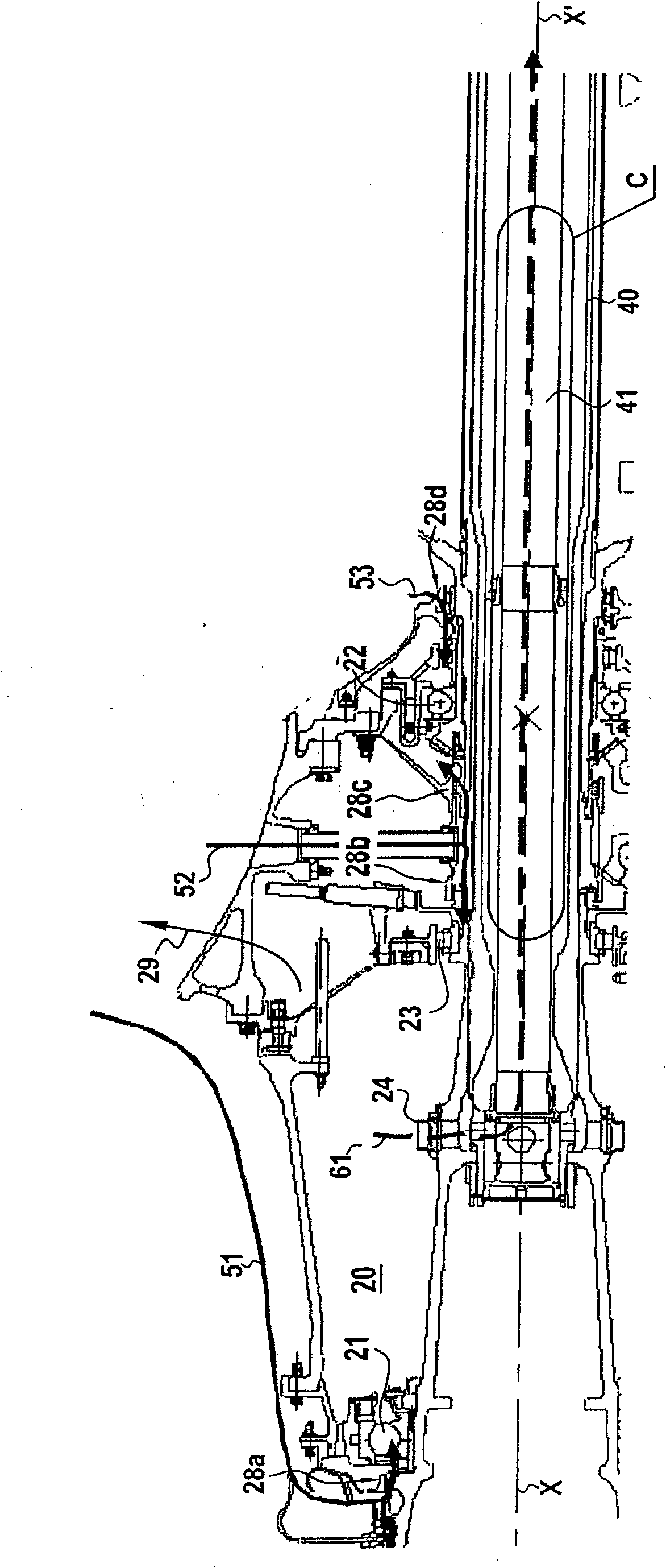
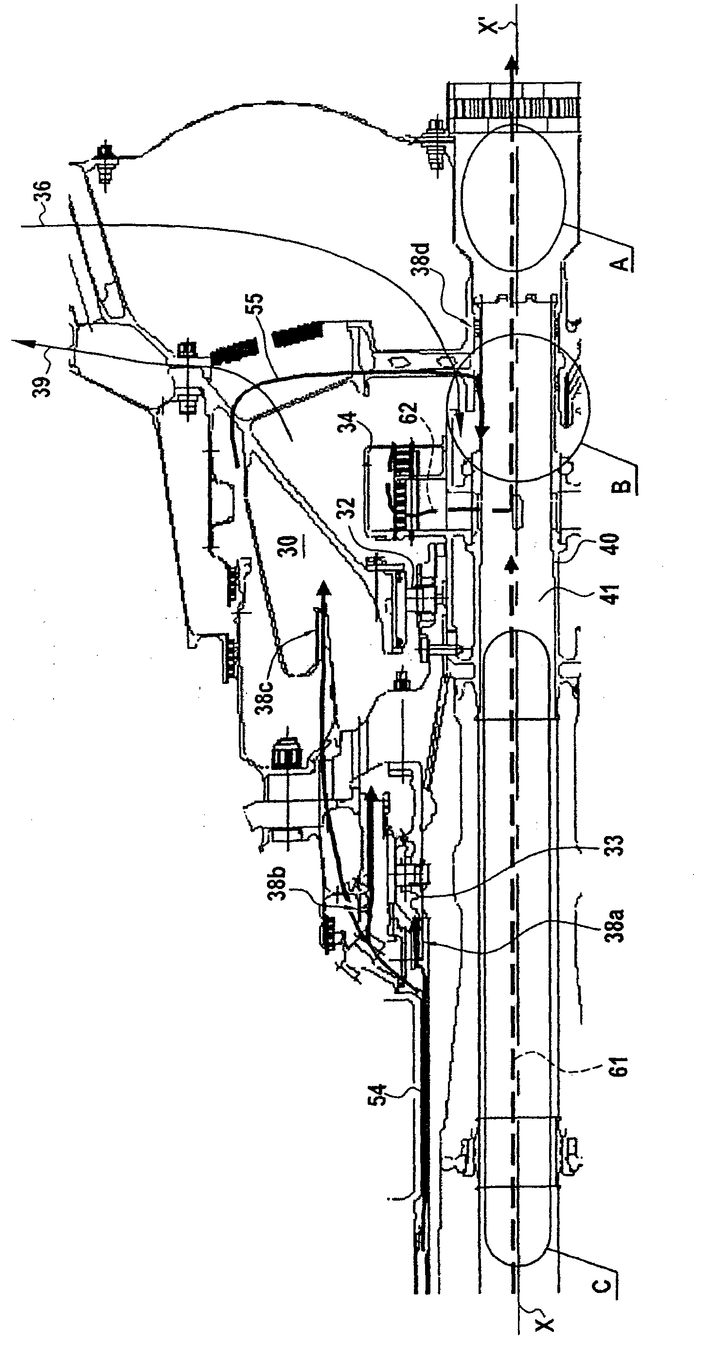
[0049] figure 1 with figure 2 The front casing 20 with the front bearings 21 , 22 and 23 and the rear casing 30 with the rear bearings 32 and 33 of the turbojet engine are shown respectively. As far as these housings are concerned, the low pressure rotor 40 includes ducts 41 to remove air and a portion of the lubricating oil entrained by the air and not trapped by the degreaser, this mixture flows through the front housing 20 and the rear housing 30 .

[0050] The position of these front and rear casings 20 and 30 in the turbojet engine is as follows Figure 14 shown.

[0051] More precisely, as figure 1 As shown, the boost line delivers three lines (arrows 51 , 52 and 53 shown in solid lines) of boost air from the drive airflow to the front housing 20 while the front housing 20 receives lubricating oil via nozzles.

[0052] This lubricating oil is mainly removed via a line that recovers the lubricating fluid (arrow 29 ) from the front housing 20 .

[0053] The chimney d...


PUM


Abstract

The invention relates to a device for balancing pressure in at least one turbojet bearing housing comprising means for supplying lubricating liquid to said bearing, air inlet means, at least one sealing system placed between the stator and the rotor at the front and / or rear of said bearing, means for recovering the lubricating liquid and means for discharging the mixture of air and lubricating liquid traces towards a degassing circuit (60). In a characteristic manner, the balancing device comprises, downstream of the bearing housing, and in the degassing circuit, a system (100) for regulating the discharged air flow that allows said flow to be variable as a function of the speed of the engine and to remain non-zero and that makes it possible to reduce the value of the air flow discharged at a high engine speed by comparison with the case where the regulating system has not been incorporated.

Description

technical field [0001] The invention relates to a method and a device for equalizing pressure in at least one bearing housing of a turbojet engine. Background technique [0002] Cases used in the field of turbojet engines, each containing rolling bearings between a rotatably mounted part and a fixedly mounted part, with oil circulation for lubricating and cooling the components. [0003] To ensure that the oil remains within the housing until it is recovered and recirculated in the lines, and to prevent it from contaminating other chambers in the engine flow section, the air within the housing is pressurized. [0004] Unfortunately, because the air has flowed through the upstream stages of the engine, it has been compressed and then injected into the casing at near-atmospheric pressure, and as a result, it contributes little or nothing to the thrust delivered by the engine. This has a detrimental effect on performance, especially in terms of fuel consumption and required th...

Claims


Application Information

Patent Timeline
IPC IPC(8): F01D25/18F01D17/14F01D17/20F01D25/16F02C7/06F02C7/28
CPCF05D2240/63F02C7/06Y02T50/671F01D25/16F01D25/183
Inventor 艾恩·芬特斯库劳伦特·吉尔吉恩-皮埃尔·莫兰
Owner SN DETUDE & DE CONSTR DE MOTEURS DAVIATION S N E C M A
Why Eureka
Try Eureka