
Device for measuring screw element at pipe end, system for measuring screw element and method for measuring screw element

一种测量装置、测量方法的技术,应用在测量装置、机械测量装置、采用光学装置等方向,能够解决自动测量困难等问题

Inactive Publication Date: 2011-02-23
NIPPON STEEL CORP +1
View PDF1 Cites 26 Cited by
  • Summary
  • Abstract
  • Description
  • Claims
  • Application Information

AI Technical Summary

Problems solved by technology

Automatic measurement is more difficult for thread elements such as hook flank A8h

Method used


Image

  • Device for measuring screw element at pipe end, system for measuring screw element and method for measuring screw element
  • Device for measuring screw element at pipe end, system for measuring screw element and method for measuring screw element
  • Device for measuring screw element at pipe end, system for measuring screw element and method for measuring screw element

Examples


Embodiment Construction

[0092] Below, refer to the attached Figure one The preferred embodiments of the present invention will be described.

[0093] First, a description will be given of the structure of a hook-shaped thread having a hook-shaped flank at the end of a threaded pipe, which is a measurement target of the thread element measuring device of the present invention. In addition, the thread element measuring device of the present invention can also measure threaded pipes having general thread shapes other than hook threads.

[0094] Image 6 Is a schematic cross-sectional view parallel to the axial direction of the pipe end on which the hook thread is formed, Figure 7 Yes Image 6 An enlarged view of one of the threads. In addition, in Image 6 with Figure 7 In order to make it easier to understand, the pitch and size of the thread are deliberately changed to be different from actual ones.

[0095] Formed as Image 6 with Figure 7 The thread A2 on the pipe end of the threaded pipe A1 as shown inc...


PUM


Abstract

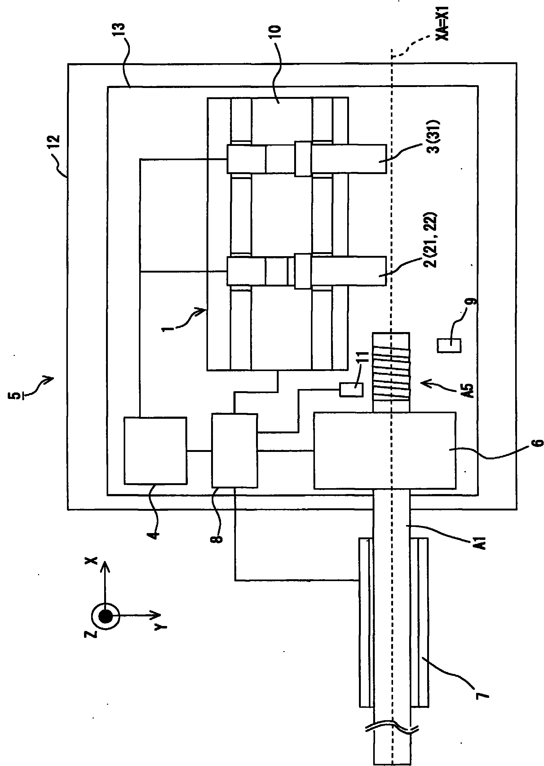
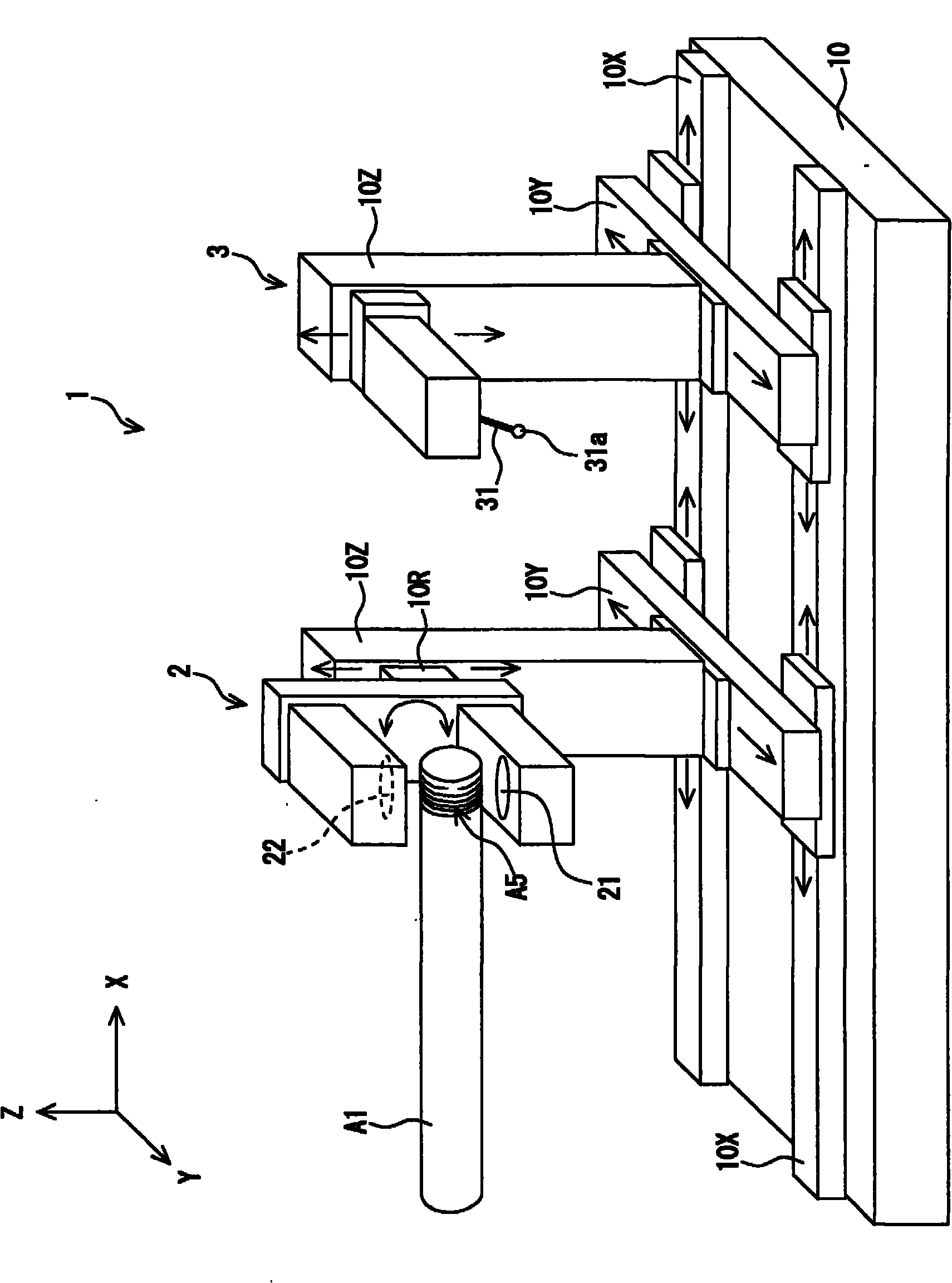
The invention provides a device for measuring screw element at pipe end, a system for measuring screw element and a method for measuring screw element. A first screw element is measured by detecting light which is substantially parallel with a screw groove (A4) among lights leaked to the side opposite to a light source (21) with respect to the axis of pipe with use of an optical sensor (2). A second screw element is measured by touching the contact probe (31) of a contact sensor (3) to the flank face (A8) of a screw and detecting the spatial coordinate of the contact probe (31) at the time ofcontact. The first and second screw elements thus detected are synthesized by an operation processing means (4) and a screw element of a measurement object screw is operated.

Description

Technical field [0001] The present invention relates to a thread element measuring device for measuring the thread element of the pipe end of a threaded pipe such as oil well pipe, and an automatic continuous processing line including a pipe manufacturing line and a finishing line that can be applied to the inspection process of the threaded pipe The thread element measuring system of the above-mentioned thread element measuring device. In addition, the present invention relates to a thread element measuring method using the above-mentioned thread element measuring device. Background technique [0002] In the past, in addition to connecting pipe ends in oil well pipes and the like, a method of forming threads on the pipe ends and using the threaded connection method has been used. With the deepening of oil wells and requirements for corrosive environments, various improvements have been made in the thread shape and other aspects of this thread (for example, refer to Non-Patent D...

Claims


Application Information

Patent Timeline
Patent Type & Authority Applications(China)
IPC IPC(8): G01B21/20G01B5/20G01B11/24
CPCG01B11/2425G01B5/163G01B11/2433G01B5/204
Inventor 本田达朗谷田睦平冈诚司加佐泰久康拉德·弗里德里希艾哈德·格吕纳
Owner NIPPON STEEL CORP
Learn More