

Circuit board connector and communication equipment
A technology for circuit boards and connectors, which is applied to the installation of connecting parts, protective grounding/shielding devices for connecting parts, and contacting parts, etc. It can solve the problems of unsatisfactory PIM of connectors and difficulty in meeting requirements, so as to reduce current density and eliminate connection The effect of not tight and good conductive effect
- Summary
- Abstract
- Description
- Claims
- Application Information
AI Technical Summary
Problems solved by technology
Method used
Image

Examples
Embodiment 1
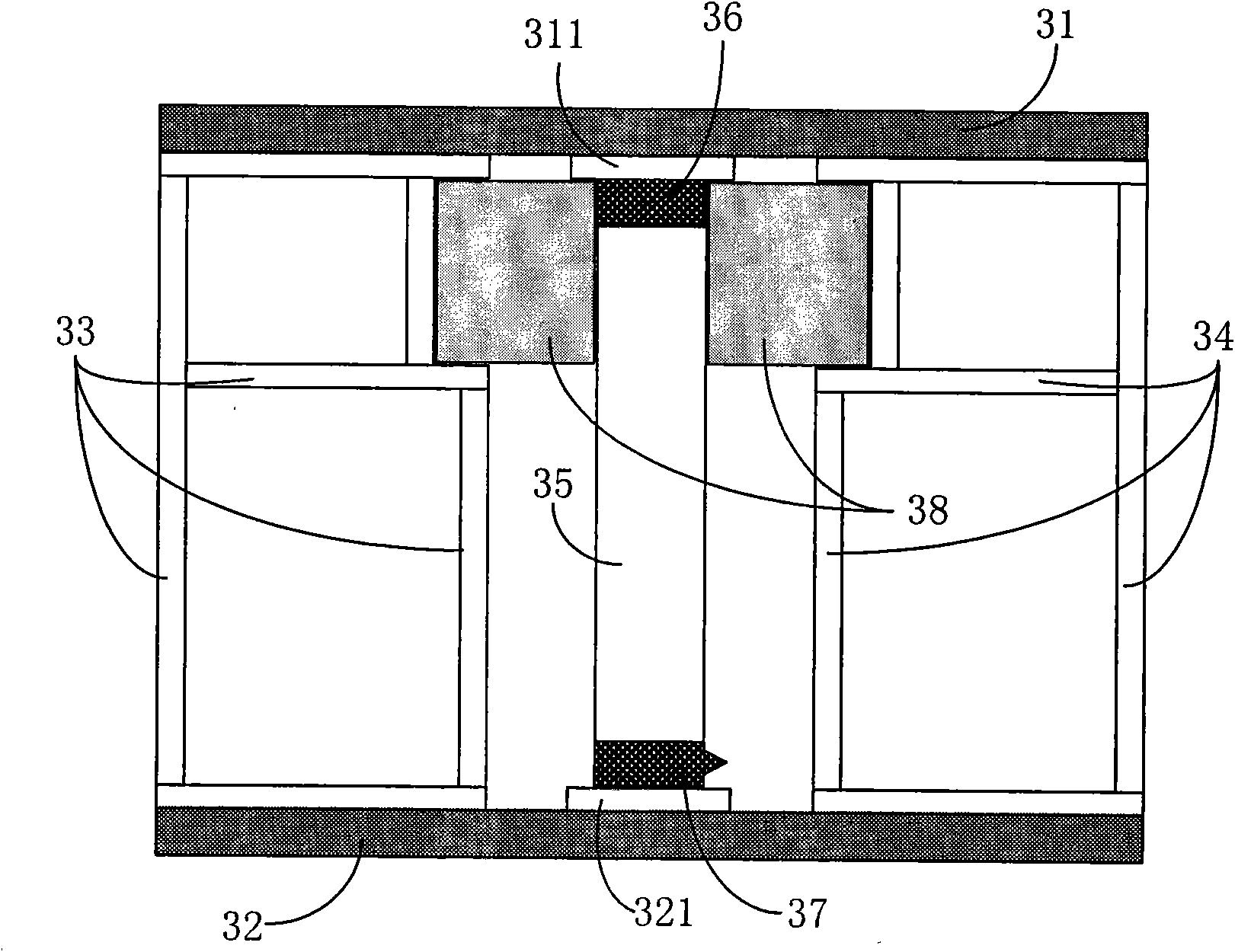
[0030] This embodiment provides a circuit board connector, which is used in a transceiver to connect an AAS module as a radio frequency connection between circuit boards, such as figure 2 As shown, the circuit board connector includes: outer conductors 33, 34, inner conductors 35 and connecting parts 36, 37;
[0031] Wherein, the outer conductor is a metal cylindrical structure, and the inner conductor 35 is a regular and uniform columnar metal body with a smooth surface, which ensures that the inner conductor has better conductive continuity. The inner conductor 35 is independent of the outer conductor and is arranged in the outer conductor. The inner conductor 35 and the outer conductor 33, 34 are filled with an insulating medium (such as air), so that the inner and outer conductors 35, 33, and 34 are separated by an insulating medium (air), which ensures that the surface current density of the inner conductor 35 is low, and the inner conductor 35 has a low surface current d...
Embodiment 2
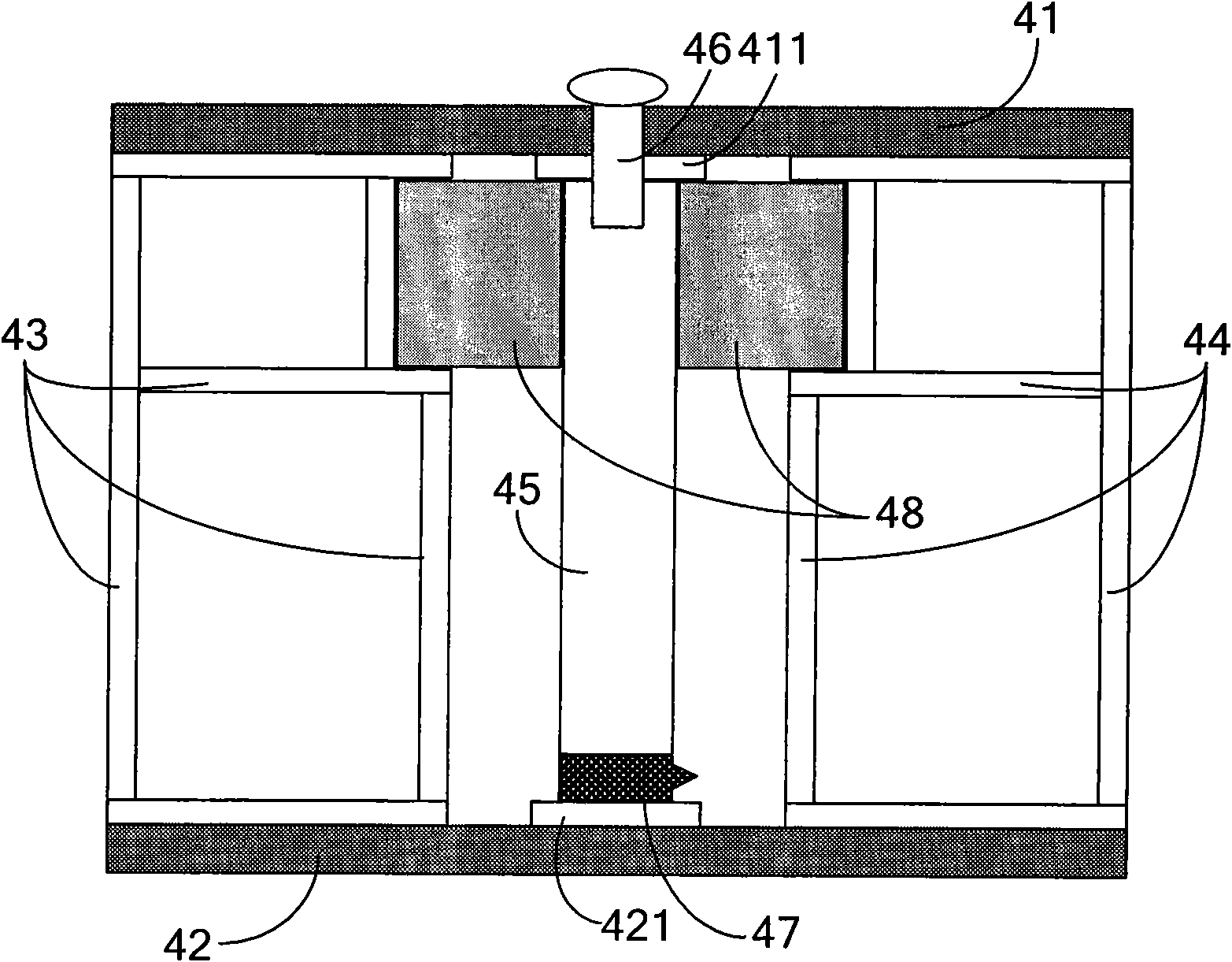
[0039] Such as image 3 As shown, the structure of the circuit board connector provided in this embodiment is basically the same as that provided in Embodiment 1, and the lower end of the inner conductor 45 of the connector still adopts a deformable conductor (such as: conductor glue, reed, spring, etc. ) as the second connecting part 47 is movably connected with the lower circuit board 42 to realize the electrical connection between the lower end of the inner conductor 45 and the surface layer metal disc 421 of the lower circuit board 42 . The difference is that the upper end of the inner conductor 45 in the connector is provided with an internal thread, which is fixedly connected with the upper circuit board 41 through the internal thread and the screw as the first connecting part 46, that is, the screw passes through the upper circuit board 41 and is screwed into the inner In the internal thread on the upper end of the conductor 45 , the upper end of the inner conductor 45 ...
Embodiment 3
[0043] Such as Figure 4 As shown, the present embodiment provides a circuit board connector, the structure of which is basically the same as that of the connector provided in Embodiment 1, and the upper end of the inner conductor 55 of the connector still adopts a deformable conductor (such as : Conductor glue, reed, spring, etc.) as the first connecting part 56 and the upper circuit board 51 movably connected, realize that the upper end of the inner conductor 55 is electrically connected with the surface layer metal disc 511 of the upper circuit board 51; the difference is that the connector The lower end of the inner conductor 55 is provided with an external thread, and through the outer thread, the lower end of the inner conductor 55 is matched with the nut 57 arranged on the lower circuit board 52 as the second connecting part 57, and is fixedly connected with the lower circuit board 52, so that the lower end of the inner conductor 55 is connected to the lower end of the i...
PUM
 Abstract
Description
Claims
Application Information