Turbocharger

A turbocharger, turboshaft technology, applied in the direction of machines/engines, engine components, mechanical equipment, etc., can solve the problems of increased manufacturing costs, accumulation, leakage, etc.

Active Publication Date: 2011-03-02
IHI CORP
View PDF1 Cites 9 Cited by
  • Summary
  • Abstract
  • Description
  • Claims
  • Application Information

AI Technical Summary

Problems solved by technology

[0011] However, in a turbocharger, if a separate sealing disk 18 is assembled to the bearing housing 3 as in the conventional example, the flow path 20 of the diffuser 19 will be caused by the bolt head of the bolt 17. The unevenness 22 generated by the portion 17a and the unevenness 23 generated by the boundary portion of the sealing disk 18, therefore, there is a problem that the air flow is disturbed and the supercharging efficiency is low.
In addition, when the sealing disk 18 is assembled, there is a possibility that scratches may be generated in the flow path 20 of the diffuser 19 where the air is pressurized by the impeller 6 due to tools or the like, The problem of low supercharging efficiency due to turbulent air flow
Furthermore, threading of the bearing housing 3, etc. will lead to an increase in processing costs, and the number of parts such as bolts 17 used in the assembly of the seal plate 18 will increase, so there is a problem of increased manufacturing costs.
[0012] In addition, although the lubricating oil flowing out from the gap 16 between the rear portion 14c of the oil control ring 14 and the outer thrust cover 4c is preferably to flow out from the space 24 between the outer thrust cover 4c and the sealing disc 18, however, Due to the high-speed rotation of the turbine shaft 5 and the oil control ring 14, there is a problem that the lubricating oil becomes mist and accumulates around the outer thrust cover 4c. Ring 15 leaks to the impeller 6 side

Method used


Image

  • Turbocharger
  • Turbocharger
  • Turbocharger

Examples


Embodiment Construction

[0048] Hereinafter, embodiments of the present invention will be described with reference to the drawings.

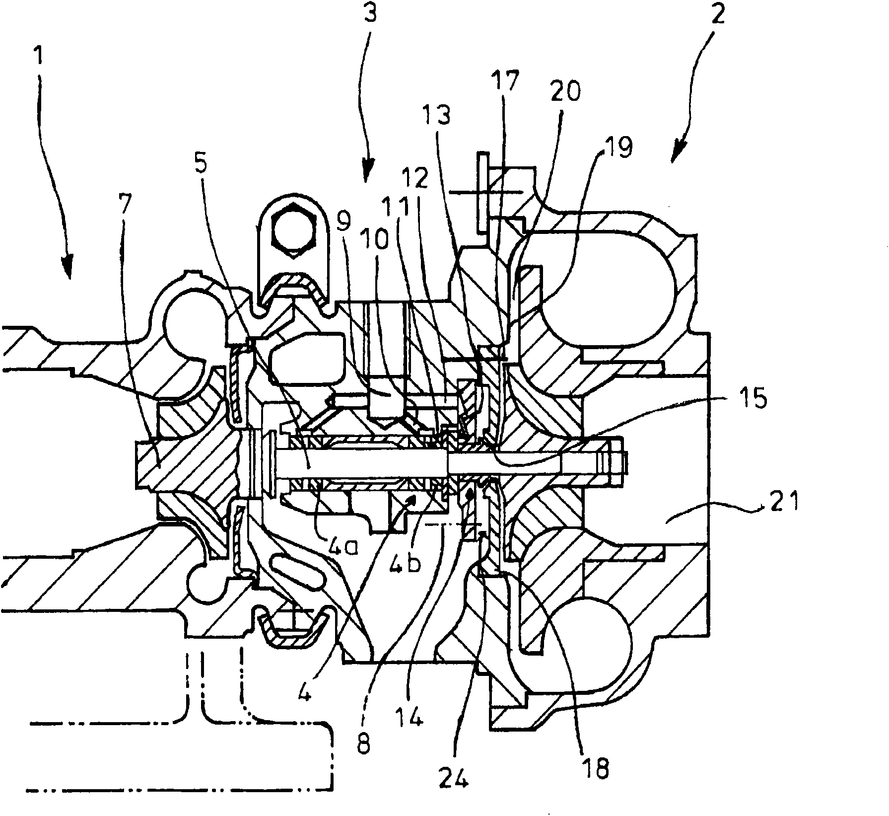
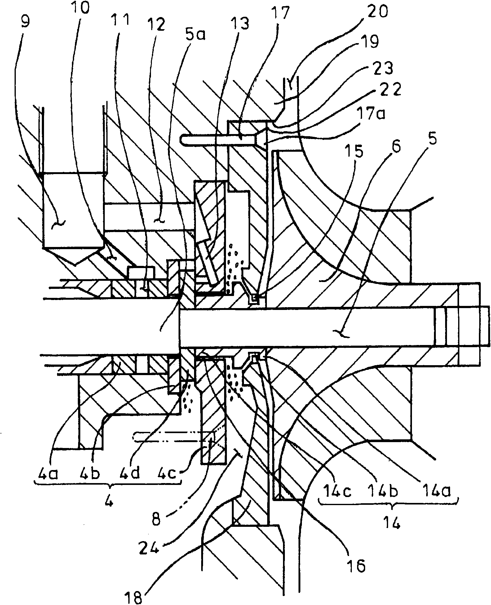
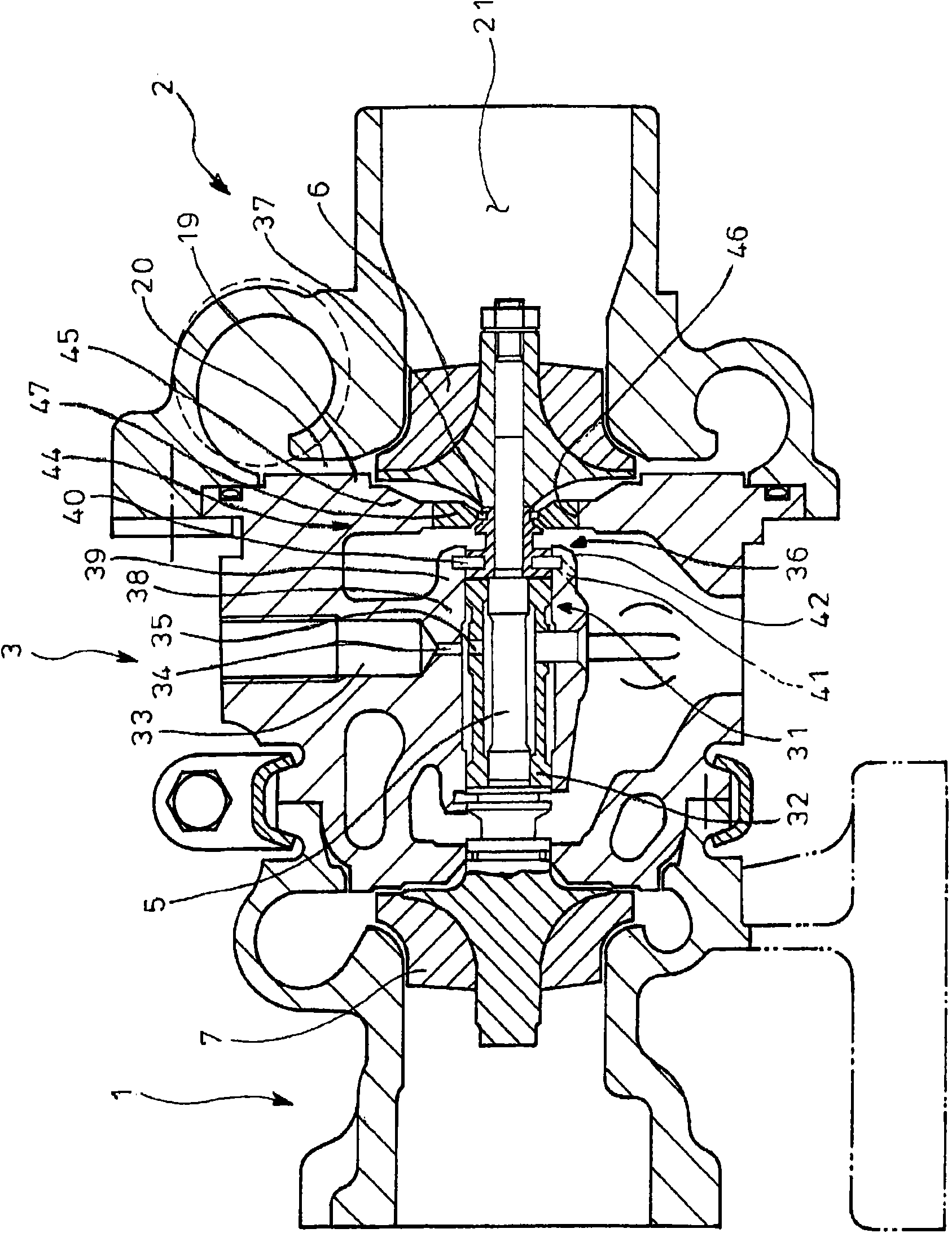
[0049] Figure 3 to Figure 10 is an embodiment of the present invention, where given with figure 1 , figure 2 The parts with the same reference numerals denote the same thing, and in order to solve the problem caused by the discharge of lubricating oil from the bearing part 4 in the past, the turbocharger according to the embodiment of the present invention is configured as follows.

[0050] The turbine shaft 5 is supported inside the bearing housing 3 image 3 , Figure 4 The bearing portion 31 is composed of a floating bush 32 having an integral structure that supports the turbine shaft 5 at two points. On the floating bush 32, lubricating oil is supplied through the supply hole 33 formed in the bearing housing 3 and the flow path 34 extending from the supply hole 33, between the floating bush 32 and the bearing housing 3, and the floating An oil film is formed ...


PUM


Abstract

In a turbocharger, an oil thrower (36) is disposed between a bearing portion (31) for supporting a turbine shaft (5) in a bearing housing (3) and an impeller (6) located in front of the bearing portion (31). A seal plate (44) which faces the outer periphery of a front part of the oil thrower (36) to prevent oil leakage from the bearing portion (31) toward the impeller (6) is formed as an integral part of the bearing housing (3) in such a manner that it may be located on the back face of the impeller (6). Moreover, an oil thrower facing portion (39) is formed in the bearing housing (3) to construct an oil reserve (40) face to face with the outer periphery of a rear part of the oil thrower (36). The seal plate (44) consists of a press-fit plate (47), and the diameter of the press-fit plate (47) is set smaller than the outer diameter of the impeller (6) and the same as or larger than a minimum bore diameter for processing the outer periphery (42) of the oil thrower facing portion (39) or for processing an oil exhaust hole (41) in the oil thrower facing portion (39).

Description

technical field [0001] The present invention relates to a turbocharger that prevents lubricating oil from leaking from a bearing portion to the impeller side. Background technique [0002] In general, turbochargers such as figure 1 , figure 2 As shown, a bearing housing 3 is integrally disposed between the turbine housing 1 and the compressor housing 2 , and the turbine shaft 5 is rotatably supported in the bearing housing 3 via a bearing portion 4 . On one side (the front side) of the turbine shaft 5, there is an impeller 6 surrounded by the compressor housing 2, and on the other side (the rear side) of the turbine shaft 5, there is an impeller 6 surrounded by the turbine housing 1. Turbine rotor 7. [0003] The bearing part 4 arranged inside the bearing housing 3 is constituted by a thrust bearing including: a floating bush 4a as a rotary bearing arranged at intervals in the axial direction of the turbine shaft 5; The inner disc 4b that moves in the axial direction; t...

Claims


Application Information

Patent Timeline
Patent Type & Authority Applications(China)
IPC IPC(8): F02B39/14F02B39/00
CPCF05D2260/37F05D2240/70F01D25/186F05D2220/40
Inventor 松山良满
Owner IHI CORP
Why Eureka
Try Eureka