
Hemodialysis concentrated liquid preparing machine

A technology of hemodialysis and concentrated solution, which is applied in the field of hemodialysis, can solve the problems that cannot overcome the pollution of hemodialysis concentrated solution, and achieve the effects of avoiding medical safety accidents, reducing labor intensity and improving work efficiency

Active Publication Date: 2012-08-15
中山本善医疗科技有限公司
View PDF0 Cites 0 Cited by
  • Summary
  • Abstract
  • Description
  • Claims
  • Application Information

AI Technical Summary

Problems solved by technology

After adopting this structure, the powder and pure water can be stirred evenly by the mixer, which greatly reduces the labor intensity of the operator, but because the liquid mixing tank is still not a closed container, it is still unable to overcome the disadvantage of the hemodialysis concentrate being polluted. It is urgent to solve the above-mentioned technical problems

Method used


Image

  • Hemodialysis concentrated liquid preparing machine
  • Hemodialysis concentrated liquid preparing machine
  • Hemodialysis concentrated liquid preparing machine

Examples


Embodiment 1

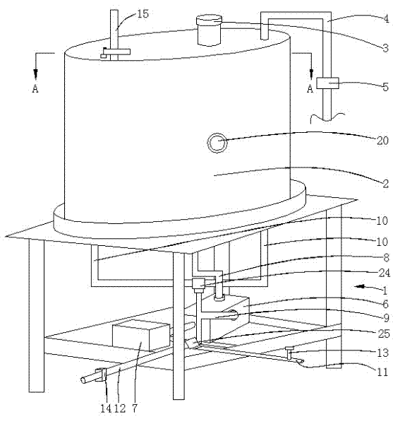
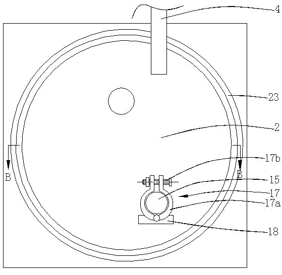
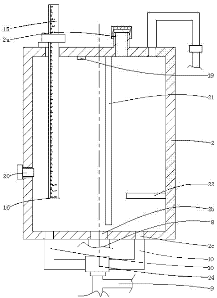
[0022] Such as Figure 1~5 As shown, a hemodialysis concentrated solution dispensing machine consists of a frame 1, a liquid dispensing barrel 2, a sealing cover 3, a water adding pipe 4, a first electromagnetic valve 5, a water pump 6, a motor 7, an outlet pipe 8, and a three-way pipe 9. Water return pipe 10, finished product liquid output pipe 11, disinfectant liquid discharge pipe 12, second solenoid valve 13, valve 14, hollow pipe 15, first liquid level sensor 16, hoop 17, fixed block 18, second liquid level Sensor 19, plugging cover 20, ultraviolet lamp 21, resistance heater 22 and other parts constitute. The frame 1 is composed of four columns 1a, four lower beams 1b, a support bar 1c and a table top 1d, wherein the four columns 1a are distributed in a rectangular shape, and the table 1d is arranged above the column 1a, and the table 1d is below the table 1d. The plate surface is fixed to the upper end surface of the column 1a, and a limit ring 23 is horizontally arrang...

Embodiment 2

[0027] refer to Figure 6 , in this embodiment, the water outlet hole 2b is opened at the center of the circular liquid dispensing barrel 2, and the right two return holes 2c are opened at the bottom of the liquid dispensing barrel 2 on the side of the water outlet hole 2b, and the other water outlet holes 2b A water return hole 2c is provided at the bottom of the liquid dispensing barrel 2 on one side. As an optimization, the centers of the three backwater holes 2c are located on the same circle, and the three backwater holes 2c are evenly arranged on the circle. The rest of the structure of this embodiment is exactly the same as that of Embodiment 1, and will not be repeated here. .

Embodiment 3

[0029] refer to Figure 7 , in this embodiment, the water outlet hole 2b is opened at the center of the circular liquid dispensing barrel 2, and the right two return holes 2c are opened at the bottom of the liquid dispensing barrel 2 on the side of the water outlet hole 2b, and the other water outlet holes 2b Two water return holes 2c are also provided at the bottom of the liquid dispensing barrel 2 on one side. As an optimization, the centers of the four backwater holes 2c are located on the same circle, and the four backwater holes 2c are evenly arranged on the circle. The rest of the structure of this embodiment is exactly the same as that of Embodiment 1, and will not be repeated here. .

[0030] The working principle of the present invention is as follows:

[0031] Before use, first close the second solenoid valve 14 on the disinfectant discharge pipe 12 and the valve 13 on the product liquid output 11, add high-concentration disinfectant into the liquid distribution ba...


PUM


Abstract

The invention discloses a liquor preparing machine for hemodialysis concentrated liquor. In the machine, a liquor preparing barrel the top of which is closed is arranged on a rack; the top of the liquor preparing barrel is provided with a feed inlet; a water adding pipe is arranged beside the liquor preparing barrel, is communicated with the inside of the liquor preparing barrel and is connected with a first solenoid valve in series; the bottom of the liquor preparing barrel is provided with a water outlet hole; the bottom parts of the liquor preparing barrel at two sides of the water outlet hole are respectively provided with a water return hole; the rack on the lower part of the liquor preparing barrel is provided with a water pump; the water pump is driven by a motor, and the water inlet of the water pump is communicated with the water outlet hole of the liquor preparing barrel by a water outlet pipe; the water outlet of the water pump is connected with a three-way pipe; one water outlet of the three-way pipe is connected with the water return pipe which is communicated with the corresponding water return hole of the liquor preparing barrel; the other water outlet of the three-way pipe is connected with a finished liquor outputting pipe and a disinfectant discharging pipe; and the disinfectant discharging pipe is connected with a second solenoid valve in series, and the finished liquor outputting pipe is connected with a valve in series. In the invention, the hemodialysis concentrated liquor which is not polluted by bacteria can be prepared under the hermetic and sterile condition.

Description

technical field [0001] The invention belongs to the technical field of hemodialysis, and in particular relates to a hemodialysis concentrated liquid dispensing machine. Background technique [0002] As we all know, the hemodialysis machine has components such as a liquid dosing pump and a conductivity detector. When it works, it needs to inhale hemodialysis concentrate (a high-concentration liquid rich in K, NA and other ions) and at the same time inhale a corresponding amount of pure water to prepare the same The dialysate with the same concentration of K and NA ions in the human body is used for hemodialysis. In the past, the dialysis powder rich in K and NA was generally added to the open liquid mixing tank first, then the corresponding amount of pure water was added, and the hemodialysis concentrate of the required concentration was prepared by purely manual stirring. Since the upper part of the liquid dispensing barrel is open, bacteria in the air can easily enter the ...

Claims


Application Information

Patent Timeline
Patent Type & Authority Patents(China)
IPC IPC(8): A61M1/14
Inventor 袁毅强
Owner 中山本善医疗科技有限公司
Learn More