Rubber stopper conveying mechanism

A technology of conveying mechanism and rubber plug, which is applied to conveyor objects, threadless plugs, transportation and packaging, etc., can solve problems such as collapse or jamming, and achieve low cost, simple and compact structure, easy guidance and different position limits. The effect of the specification

Active Publication Date: 2011-03-16
TRUKING TECH LTD
View PDF6 Cites 1 Cited by
  • Summary
  • Abstract
  • Description
  • Claims
  • Application Information

AI Technical Summary

Problems solved by technology

However, when the upper plug plate rotates to convey the rubber plug, under the action of sliding friction between the rubber plug and the fence, the rubber plug will be squeezed into the escape groove with a smaller diameter, which is prone to collapse or jamming

Method used


Image

  • Rubber stopper conveying mechanism
  • Rubber stopper conveying mechanism
  • Rubber stopper conveying mechanism

Examples


Embodiment Construction

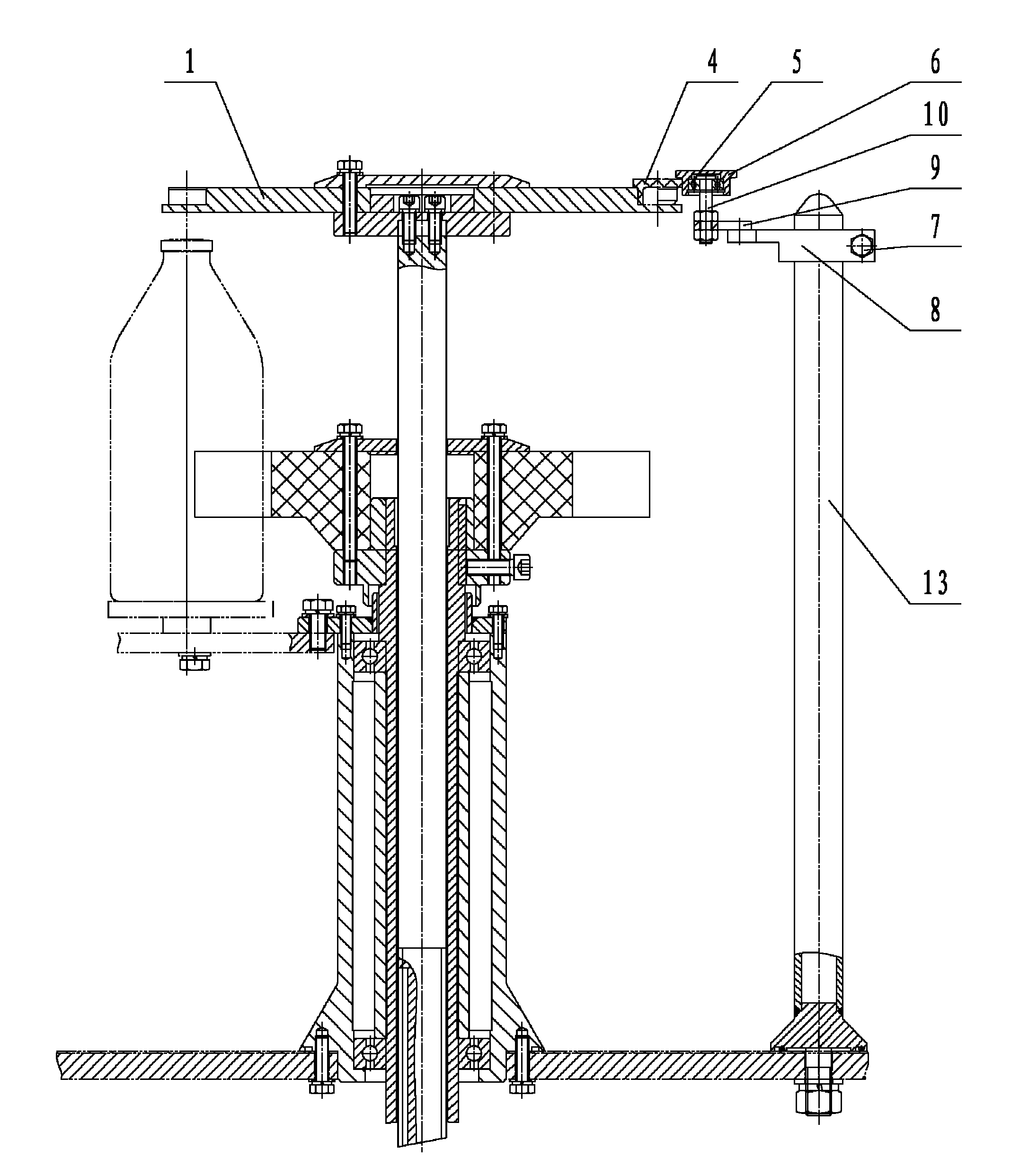
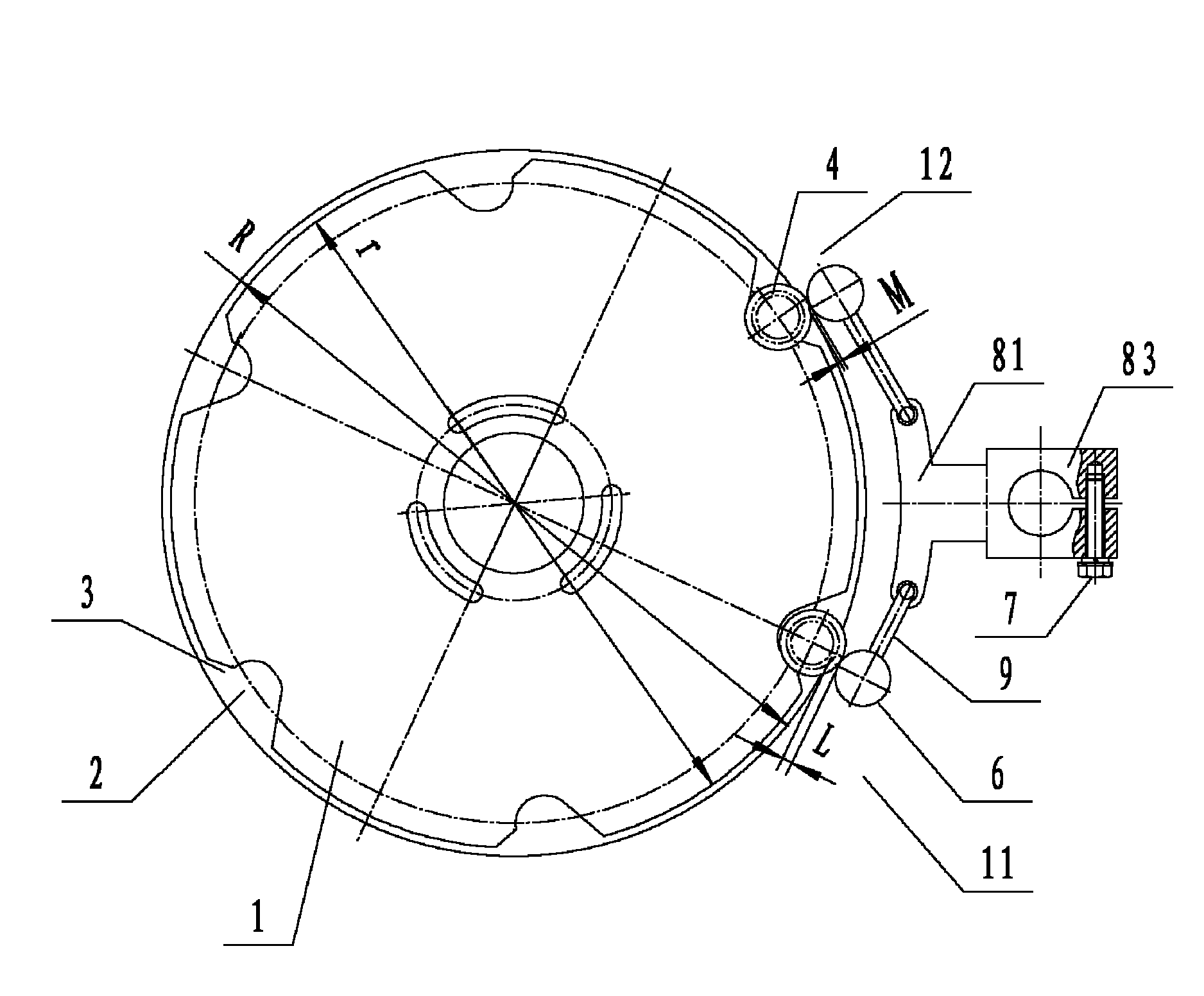
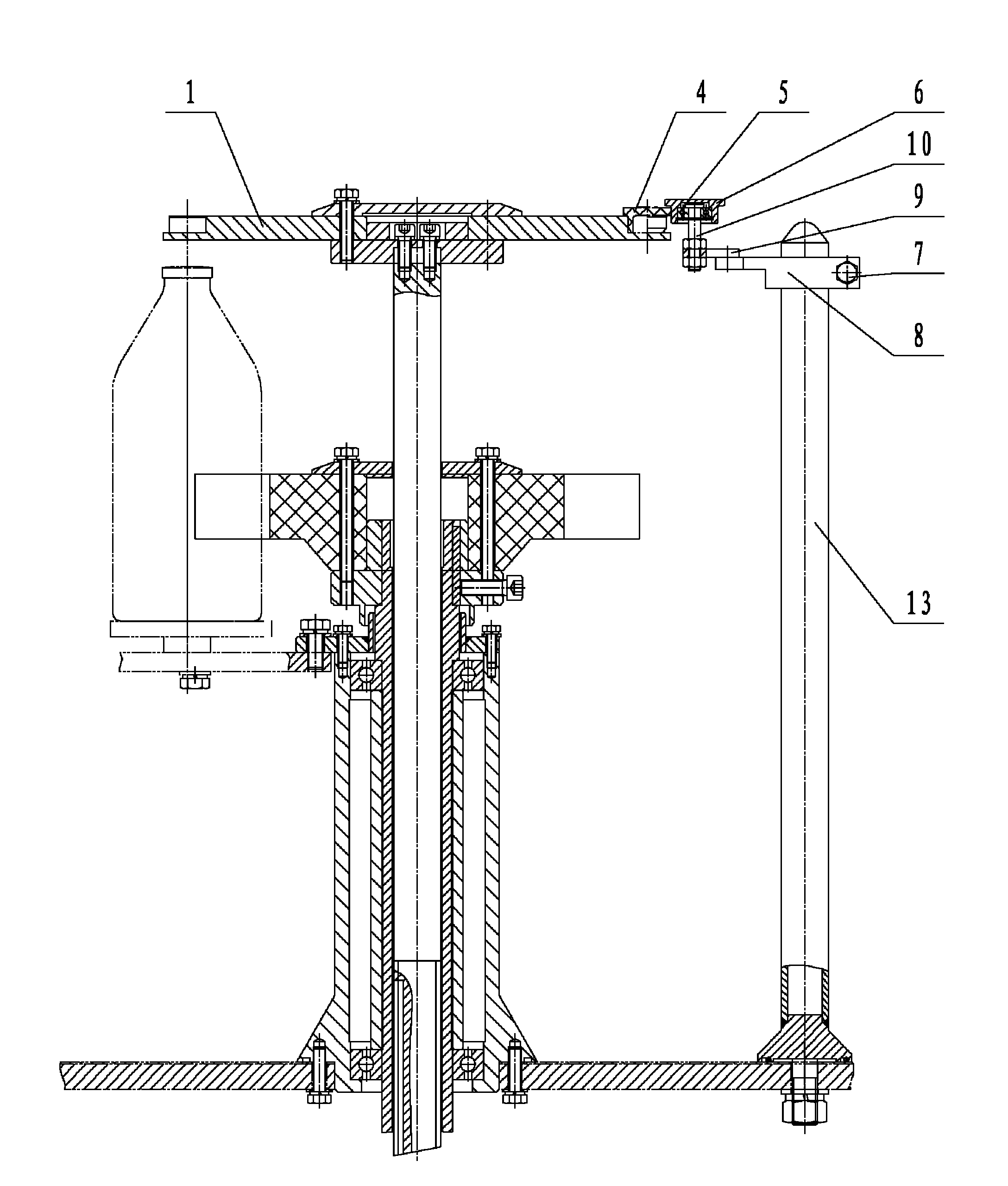
[0020] figure 1 and figure 2 It shows an embodiment of a rubber stopper conveying mechanism of the present invention, the mechanism includes an upper stopper plate 1, and the outer edge of the upper stopper plate 1 is provided with a stopper accommodating groove 2 and an avoidance groove 3 connected with the stopper accommodating groove 2 , The periphery of the upper plug disc 1 is provided with a rolling member 5 for guiding and limiting the rubber plug 4 in the plug accommodating groove 2 . The rubber plug conveying mechanism of the present invention has a simple and compact structure and low cost. During the process of the upper plug plate 1 rotating and conveying the rubber plug 4, only a rolling friction force is generated between the rubber plug 4 and the rolling member 5, and the rolling friction force is relatively small Instead of driving the rubber plug 4 to squeeze into the escape groove 3 with a smaller diameter, the phenomenon of plugging or jamming can be avoid...


PUM


Abstract

The invention discloses a rubber stopper conveying mechanism which comprises an upper stopper disc, wherein the periphery of the upper stopper disc is provided with a rubber stopper accommodating slot and an avoiding slot connected with the rubber stopper accommodating slot; and the circumference of the upper stopper disc is provided with a rolling piece for guiding and limiting a rubber stopper in the rubber stopper containing slot. The rubber stopper conveying mechanism has the advantages of simple and compact structure, low cost, and capability of preventing the collapsing or locking of the rubber stopper.

Description

technical field [0001] The invention relates to the field of pharmaceutical and food packaging machinery, in particular to a rubber stopper conveying mechanism. Background technique [0002] In the fields of pharmaceutical and food packaging machinery, nitrogen filling stoppering machines have been widely used. The existing rubber stopper conveying mechanism of the nitrogen-charging stoppering machine comprises an upper stopper plate and a fence arranged in the circumferential direction of the upper stopper plate. When working, the rubber plug enters the rubber plug accommodating groove of the upper plug disc from the previous station, and is rotated together with the upper plug disc under the guide and limit of the fence to be transported to the nitrogen filling and plugging station, and then the nitrogen filling and plugging Take out the rubber stopper by vacuum suction at the station. In the process of taking out the rubber plug from the rubber plug storage groove of th...

Claims


Application Information

Patent Timeline
IPC IPC(8): B65B7/28B65G47/84B67B1/04
Inventor 李鹏程杨小胜龙煌辉刘振唐岳
Owner TRUKING TECH LTD
Why Eureka
Try Eureka