Air speed step indicating circuit of electric fan

A technology for indicating circuits and electric fans, applied in pump control, non-variable-capacity pumps, machines/engines, etc., can solve problems such as many failures, high cost, and large size

Active Publication Date: 2011-03-16
江门市金羚排气扇制造有限公司
View PDF9 Cites 2 Cited by
  • Summary
  • Abstract
  • Description
  • Claims
  • Application Information

AI Technical Summary

Problems solved by technology

Although the design is eye-catching and easy to observe, the 2-pole multi-position contact switch used is large in size, high in cost and has many faults

Method used


Image

  • Air speed step indicating circuit of electric fan
  • Air speed step indicating circuit of electric fan
  • Air speed step indicating circuit of electric fan

Examples


Embodiment Construction

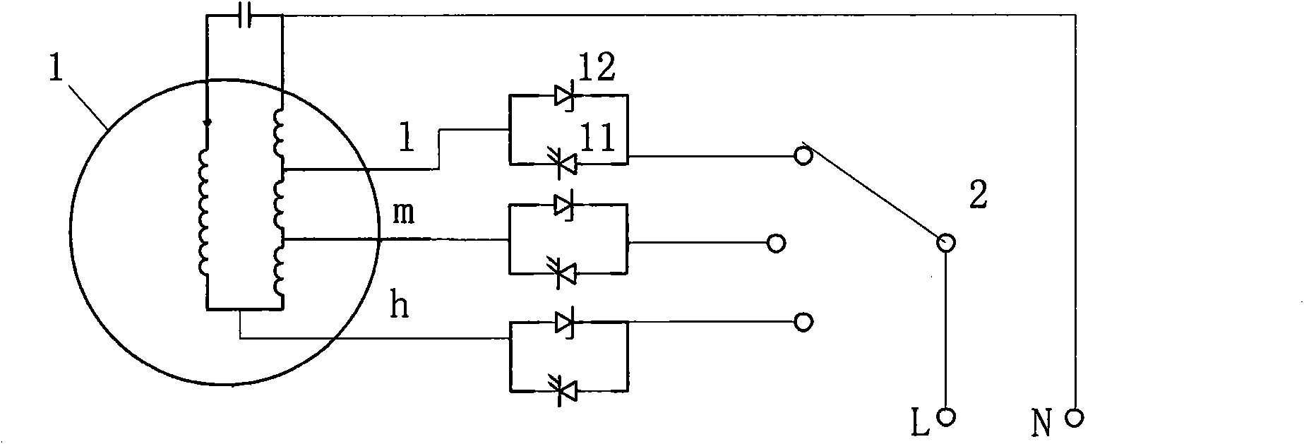
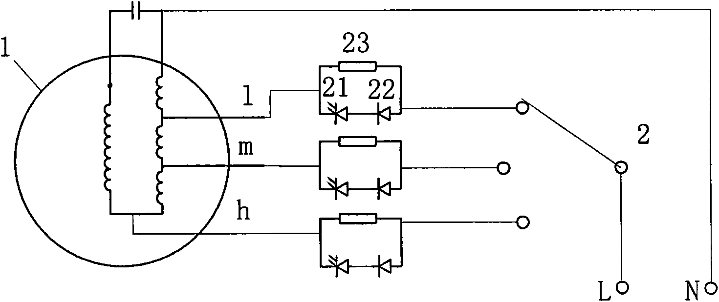
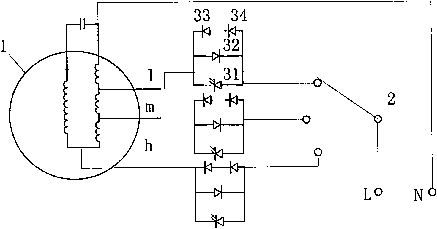
[0009] Embodiments 1 to 3 of the present invention electric fan circuit such as figure 1 , 2 As shown in and 3, they are all connected to the L and N poles of the single-phase power supply, and the unipolar 3-position switch 2 performs speed regulation and switching control on the h, m and 1 taps of the motor 1 winding. These 3 embodiments are all improved on the basis of the embodiments described in the Chinese utility model patent specification whose application number is 99203621.6 and publication number is CN2379629, and the electric fan motor is a single-phase capacitor running motor and a main phase tap speed regulation, rated The voltage is 220V, the rated input power is 40W, and the measured currents of the h, m and 1 gears are 0.170A, 0.184A and 0.203A when the prototype is running under the rated voltage. Major improvements include:

[0010] ——The double step switch 2 of the described embodiment is changed to a single-pole multi-position switch, and the three branc...


PUM


Abstract

The invention discloses an air speed step indicating circuit of an electric fan. The circuit comprises a single-pole multi-position switch, wherein a common terminal of the single-pole multi-position switch is connected with one pole of a power supply; each terminal is connected with each speed adjusting tap of a motor winding of the electric fan; the circuit is characterized in that: each terminal of the switch is connected with each speed adjusting tap of the motor winding of the electric fan through a low-impedance circuit; the low-impedance circuit is a parallel circuit consisting of a plurality of branches, of which one branch is one light emitting diode or is formed by connecting one light emitting diode and other elements in series; and the low impedance is within 5 percent of the impedance of a corresponding speed adjusting tap loop of the motor winding of the electric fan. Through the design, the two-pole multi-position switch in the prior art can be substituted by the single-pole multi-position switch, so that the structure is simplified, and the cost and the failure are reduced.

Description

technical field [0001] The invention relates to a wind speed classification indicating circuit of an electric fan, and the international patent classification belongs to F04D27 / 00. Background technique [0002] The wind speed classification indication circuit of the traditional electric fan is to set a direct mechanical gear position indication mark for the movement mechanism of the contact speed control switch, which is inconvenient to observe because the mark is not eye-catching. Afterwards, the existing technology was changed to use light-emitting diodes to indicate the speed gear, and a 2-pole multi-position contact switch was used as the speed control switch, one pole was used to switch the speed control taps of the electric fan motor winding, and the other pole was used for Switch the light-emitting diode branch to indicate the speed gear. The specific design can be seen in the Chinese utility model patent whose application number is 99203621.6 and publication number i...

Claims


Application Information

Patent Timeline
Patent Type & Authority Applications(China)
IPC IPC(8): F04D27/00
CPCF04D27/004
Inventor 叶露微
Owner 江门市金羚排气扇制造有限公司
Why Eureka
Try Eureka