Fixed device of horizontal blocking rod of combined bedstead
A fixing device and crosspiece technology, which is applied in the direction of bed frames, other seating furniture, household appliances, etc., can solve the problem of affecting the quality of the embedded crosspiece, the difficulty of processing the embedded crosspiece, and the application of high pressure, etc. problems, to achieve the effect of easy mold opening and manufacturing, improved support capacity, and reduced cross-sectional area
- Summary
- Abstract
- Description
- Claims
- Application Information
AI Technical Summary
Problems solved by technology
Method used
Image
Examples
Embodiment 1
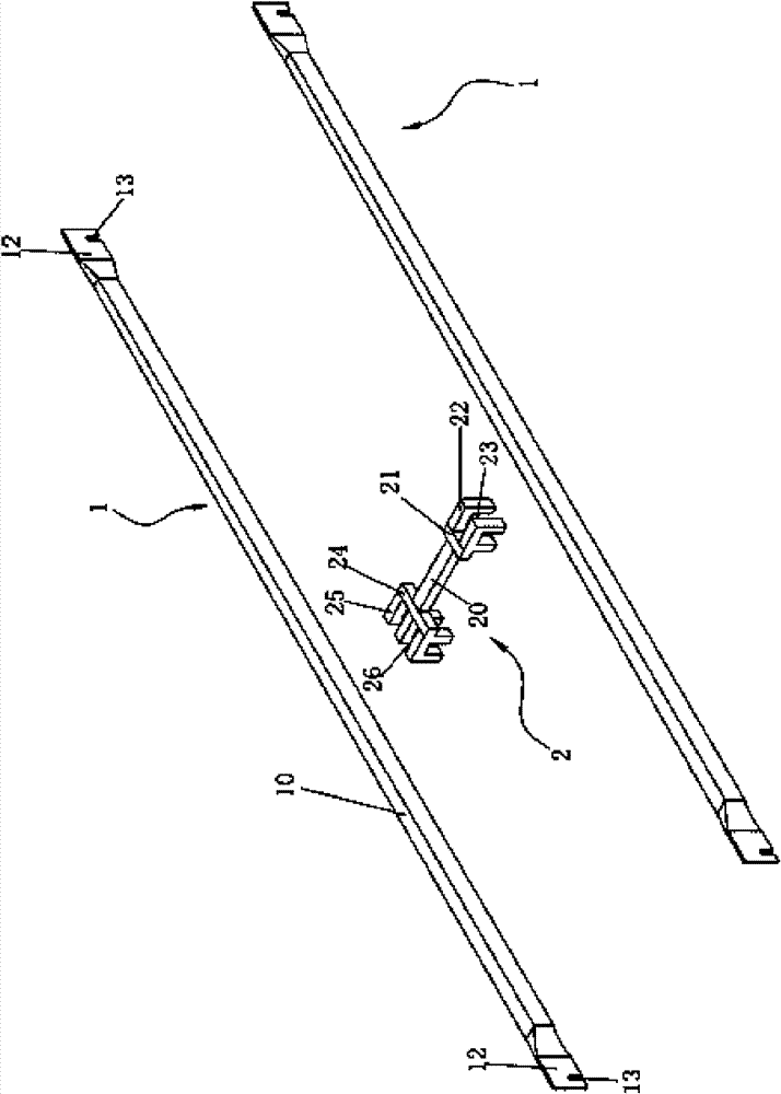
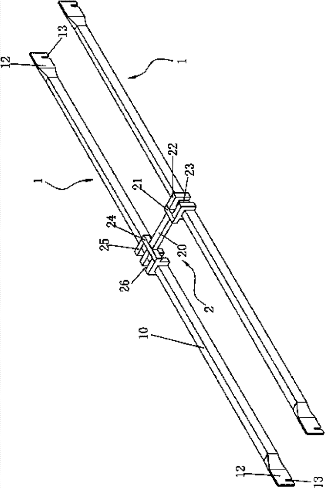
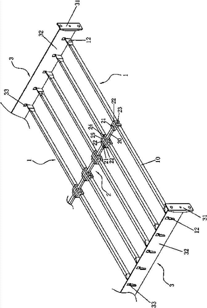
[0021] An embodiment of the fixing device of the present invention's combined bed frame cross bar, see figure 1 , is a clip 2 for fixing the distance between adjacent cross bars 1 .
[0022] The cross bar 1 applicable to this embodiment adopts a metal tube with a rectangular cross-section, which is cut into a tubular body 10 according to the required length. Both ends of the main body 10 are respectively extruded into sheet-shaped clamping portions 12 , and slots 13 are respectively opened on the lower edges of the two clamping portions 12 .
[0023] The middle part of the snap connector 2 is a rod 20 . The first end 21 of the rod 20 is provided with two claws 22 side by side, leaving a space 23 between the two claws 22; the second end 24 of the rod 20 is provided with three claws 25 side by side, and two adjacent claws Spaces 26 are left between the claws 25 . The claws 22 on the first end 21 of the snap connector 2 and the claws 25 on the second end 25 are arranged in a s...
Embodiment 2
[0037] The second embodiment of the fixing device for the cross bar of the combined bed frame of the present invention is suitable for the embedded cross bar which is easier to process than the rectangular section embedded cross bar. The three-dimensional structure of the snap connector 200 in this embodiment and the two crossbars 100 connected to it is as follows: Figure 8 shown.
[0038] The cross bar 100 applicable to this embodiment adopts a metal round tube, which is cut into a tubular body 1000 according to the required length. A process hole 1100 is respectively provided near two ends of the body 1000 . Two ends of the main body 1000 are located outside the corresponding process holes 1100 and are respectively extruded into sheet-shaped clamping parts 1200 , and card slots 1300 are respectively opened on the lower edges of the two clamping parts 1200 .
[0039] A rod 2000 is formed in the middle of the snap connector 200 . The first end 2100 of the rod 2000 is provi...
PUM
 Abstract
Description
Claims
Application Information
 - R&D
- Intellectual Property
- Life Sciences
- Materials
- Tech Scout
- Unparalleled Data Quality
- Higher Quality Content
- 60% Fewer Hallucinations
Browse by: Latest US Patents, China's latest patents, Technical Efficacy Thesaurus, Application Domain, Technology Topic, Popular Technical Reports.
© 2025 PatSnap. All rights reserved.Legal|Privacy policy|Modern Slavery Act Transparency Statement|Sitemap|About US| Contact US: help@patsnap.com


