
Rubber diaphragm circular vulcanizing device for brake chamber in automobiles

A technology of rubber diaphragm and automobile braking, applied in household components, household appliances, other household appliances, etc., can solve the problems of long production cycle, low production efficiency, low equipment utilization rate, etc., to simplify production operations, improve quality, Effects for easy setup and control

Active Publication Date: 2011-03-23
NINGGUO HAI TIAN LI IND DEV
View PDF5 Cites 15 Cited by
  • Summary
  • Abstract
  • Description
  • Claims
  • Application Information

AI Technical Summary

Problems solved by technology

[0002] The existing secondary vulcanization molding process of the rubber diaphragm of the automobile brake chamber is a single-person single-machine operation mode. During operations such as putting materials and canvas in, the forming press waits idlely, and when the forming press performs two vulcanization molding processes of the rubber diaphragm, the operator waits idlely. Therefore, the existing rubber diaphragm forming process has a long production cycle and equipment Defects such as low utilization rate and low production efficiency

Method used


Image

  • Rubber diaphragm circular vulcanizing device for brake chamber in automobiles
  • Rubber diaphragm circular vulcanizing device for brake chamber in automobiles
  • Rubber diaphragm circular vulcanizing device for brake chamber in automobiles

Examples


Embodiment Construction

[0023] The present invention will be described in detail below in conjunction with the examples.

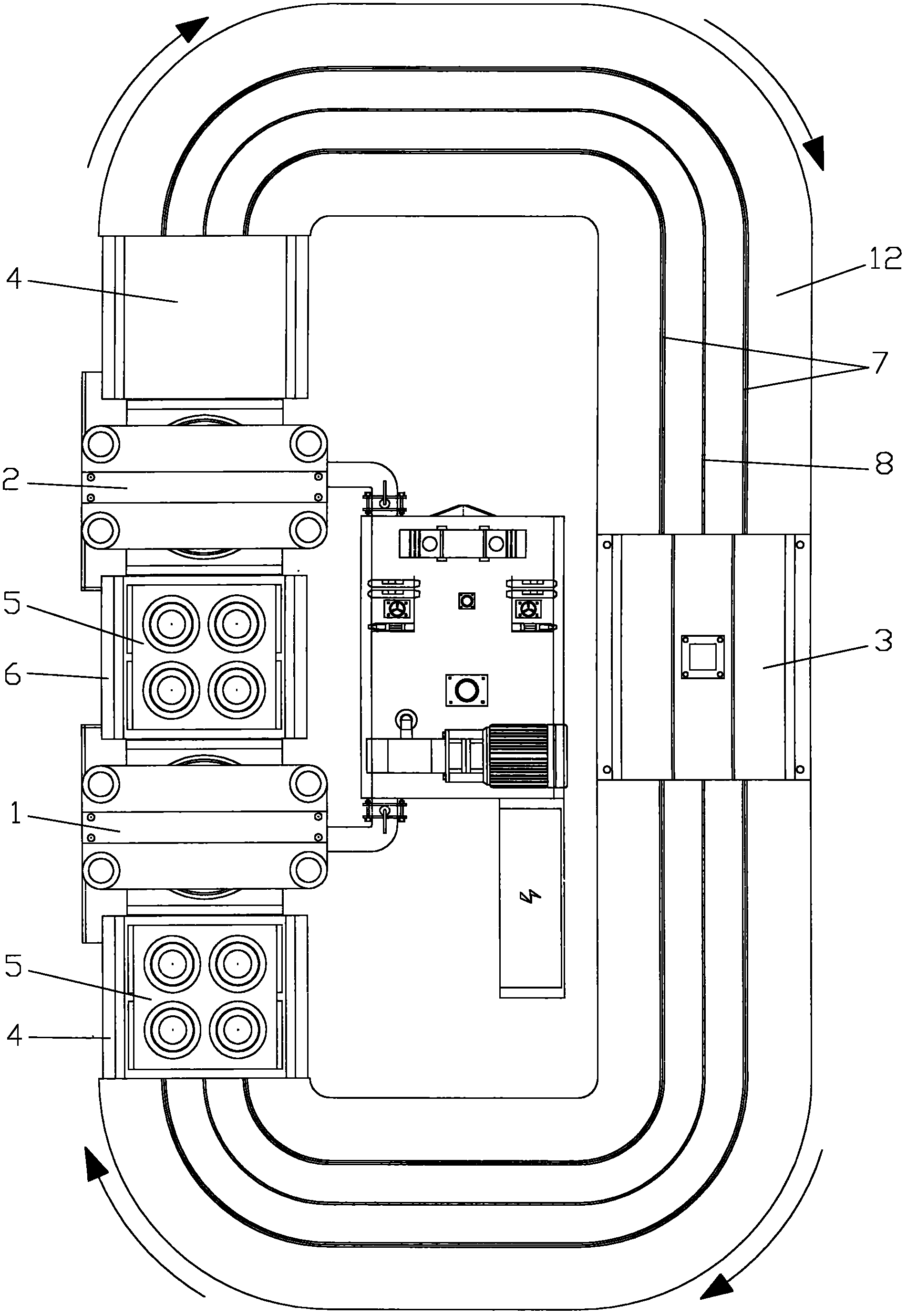
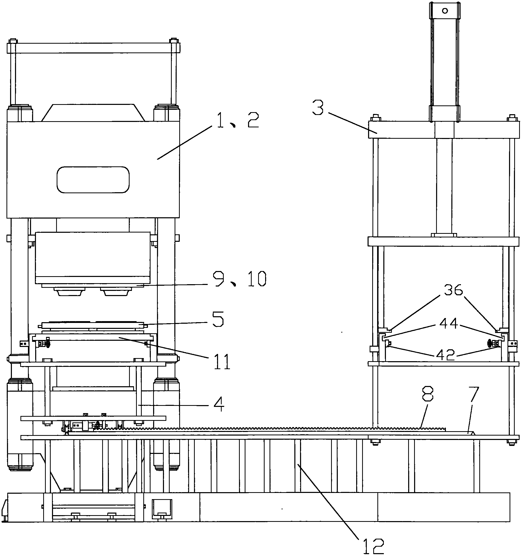
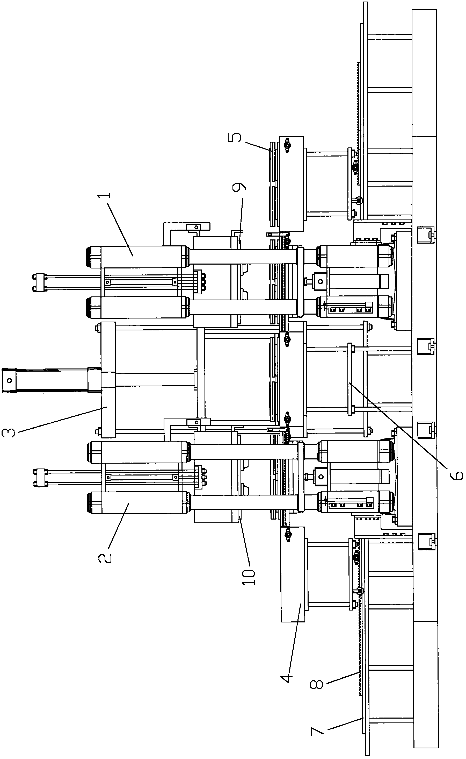
[0024] Such as Figure 1-Figure 9 As shown, the automobile brake air chamber rubber diaphragm cycle vulcanization device of the present invention includes a first vacuum vulcanization press 1, a second vacuum vulcanization press 2, a demoulding mechanism 3, and a rubber diaphragm vulcanization molding die, wherein the rubber diaphragm vulcanization molding die It is a compound mold structure including four sets of rubber diaphragm vulcanization molding units, including lower mold, middle mold, first upper mold, second upper mold, lower mold, pressure ring, upper mold for primary vulcanization and secondary mold in each unit. The upper mold for vulcanization is respectively arranged on the lower mold plate, the middle mold plate, the first upper mold plate and the second upper mold plate.

[0025] The first press 1 is used for the primary vulcanization treatment of the rubber dia...


PUM


Abstract

The invention discloses a rubber diaphragm circular vulcanizing device for a brake chamber in automobiles. The device comprises first press, a second press, a demolding mechanism and a rubber diaphragm molding die, wherein the first press is used for performing primary vulcanizing treatment on the rubber diaphragm; the second press is used for performing secondary vulcanizing treatment on the rubber diaphragm; the demolding mechanism is used for separating a press ring and a lower die in the rubber diaphragm molding die; and a medium transmission mechanism is arranged between each press and the demolding mechanism, and a transition rail is arranged between the presses, so that a worktable closed moving loop from the first press to the second press to the demolding mechanism and to the first press is formed. In the device, the flow production of the rubber diaphragm can be realized by setting the two presses and the medium transmission mechanisms, the equipment utilization rate is improved, and the production operation is simplified, so the conventional single-person single-machine production mode can be changed into a mode that two persons operate four or more machines. Furthermore, primary vulcanizing treatment and secondary vulcanizing treatment on the rubber diaphragm are completed by the two presses respectively, and the setting and control of vulcanizing parameters are facilitated.

Description

technical field [0001] The invention relates to a secondary vulcanization molding device for a rubber diaphragm in an automobile brake air chamber, in particular to a vulcanization device capable of cyclically processing the rubber diaphragm. Background technique [0002] The existing secondary vulcanization molding process of the rubber diaphragm of the automobile brake chamber is a single-person single-machine operation mode. During operations such as putting materials and canvas in, the forming press waits idlely, and when the forming press performs two vulcanization molding processes of the rubber diaphragm, the operator waits idlely. Therefore, the existing rubber diaphragm forming process has a long production cycle and equipment Defects such as low utilization rate and low production efficiency. Contents of the invention [0003] In view of the problems existing in the prior art, the object of the present invention is to provide a rubber diaphragm cycle vulcanizati...

Claims


Application Information

Patent Timeline
Patent Type & Authority Applications(China)
IPC IPC(8): B29C35/02B29C43/36B29C43/32B29C43/50B29C43/58B29L31/16
Inventor 柳青山
Owner NINGGUO HAI TIAN LI IND DEV
Learn More