Panel mounting device, mounting method and mounting accessory

A technology for installing devices and panels, which is applied to heating devices, solar thermal devices, and roofs using flat/curved panels, etc., can solve the problems of poor construction, shorten the durability of the roof, and high cost, and achieve the effect of improving construction.

Active Publication Date: 2011-03-23
YUGENKAISHA HANATANIKOUGYOU
View PDF4 Cites 8 Cited by
  • Summary
  • Abstract
  • Description
  • Claims
  • Application Information

AI Technical Summary

Problems solved by technology

However, there will be the following problems: the cost of the components of the scaffold is high, and the work of installing the scaffold to the roof is cumbersome and labor-intensive, requiring construction time and construction costs; There may be rain leakage due to holes; or the roof needs to be reinforced because the scaffolding is made of heavy components such as steel bars
[0004] However, in the mounting fitting described in Patent Document 1, since the number of parts is large, the cost is high, and bolts and nuts need to be tightened when the mounting fitting is installed, there are not only tools such as a wrench, but also troublesome work and difficult construction. Poor performance, labor-intensive and long construction time
Moreover, when adjusting the installation position of the installation accessories relative to the curling portion, it is very troublesome to loosen and tighten the bolts and nuts one by one.
In particular, when many solar panels are installed in order to obtain a large amount of power, such as a workshop, it takes a lot of labor and time to install many installation accessories.
In addition, when installing a panel on the roof to accommodate the plant soil for greening the roof, as above, it is generally installed by piercing the bolt penetration holes for scaffolding on the roof plate, and there is a risk that the roof will be shortened due to rain leakage. The question of the number of years of durability

Method used


Image

  • Panel mounting device, mounting method and mounting accessory
  • Panel mounting device, mounting method and mounting accessory
  • Panel mounting device, mounting method and mounting accessory

Examples


Embodiment Construction

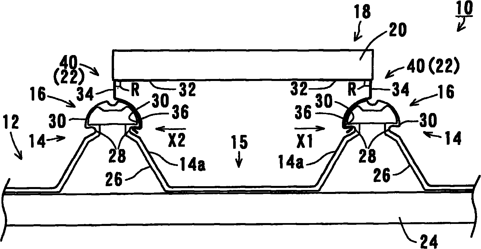
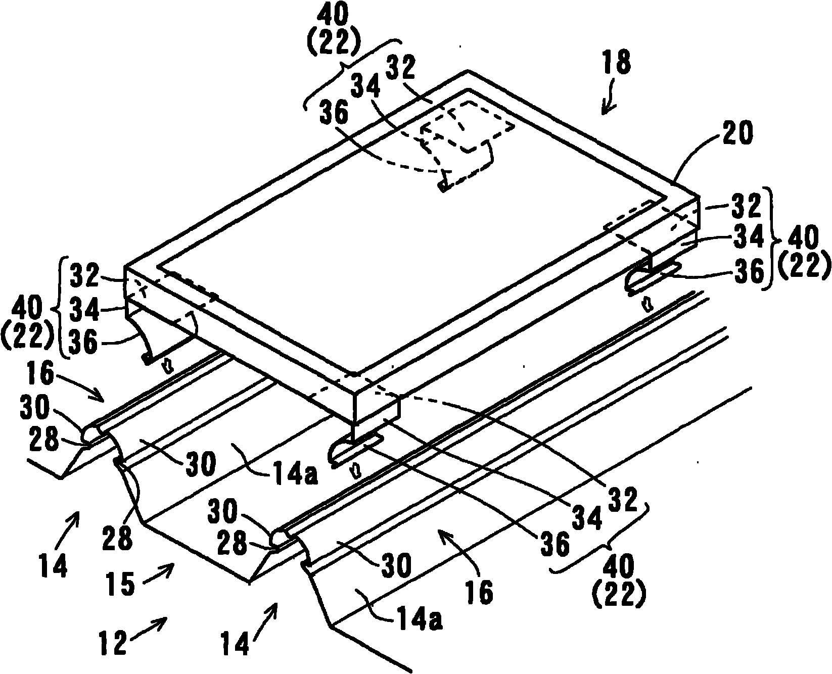
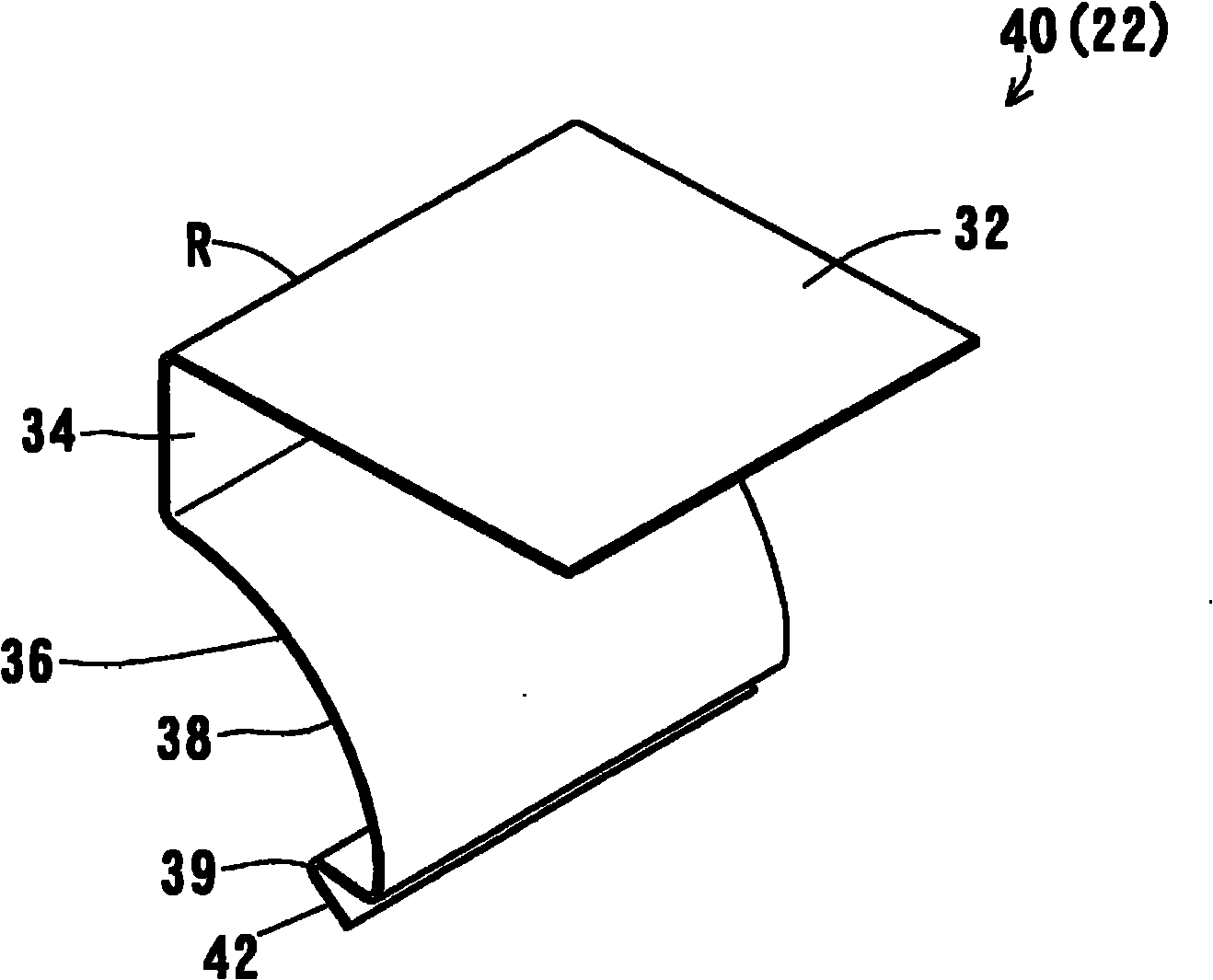
[0050] Hereinafter, embodiments of the panel mounting device, mounting method, and mounting accessories of the present invention will be described with reference to the drawings. The panel installation device, installation method and installation accessories of the present invention are suitable, for example, for installing panels including solar cell panels or plant soil storage panels for greening on folded plate roofs that constitute the roofs of structures such as ordinary houses, garages, workshops, and public facilities. panel. The drawings show embodiments of the present invention. In these embodiments, the panels mounted on the roof are exemplified by solar battery panels or greening plant soil storage panels. In the figure, the solar cell module, the earth and the plants planted on the earth are not shown, and only a flat quadrangular case is shown for simplification, so that it is easier to grasp from the figure. In addition, a solar cell (Solar Cell) panel is an el...


PUM


Abstract

The present invention provides a panel mounting device, a mounting method and a mounting accessory, which can perform construction through simple operation with simple structure and low cost. The panel mounting device is characterized by comprising the following components: hilling mounting parts (16) which are formed at the upper part of each hill part (14), connect roof material of a folded plate with roof structure material and continuously connect thin neck parts (28) with projections (30) thereby forming at two sides of the hill part (14), wherein, the thin neck parts (28) shrinks from the hill (14) body in a direction of reducing the width of the hill, and the projection (30) projects outwards from the thin neck part (28) in a direction of enlarging the width of the hill; a supporting frame (20) of the panel (18); and a plurality of elastic jointing parts (22) which are provided at the supporting frame (20), are simultaneously snapped with the hill connection parts (16) of the opposite hills (14) and are jointed with the hill connection parts, wherein a force can be elastically exerted with a mode of pushing the hill connection parts (16) sideways through the pushing operation of the panel (18) from top to bottom.

Description

technical field [0001] The invention relates to a panel installation device, installation method and installation accessories for installing panels such as solar cell panels or greening plant soil storage panels on a folded plate roof. Background technique [0002] Currently, the use and development of clean energy with little environmental load is being promoted, and as one of them, solar cell panels are installed on the roof or roof terrace of houses, workshops, public facilities, and the like. In the past, the construction of installing solar panels on the roof was to install the solar panels on the scaffolding (Japanese: pedestal) fixed to the roof with bolts. However, there will be the following problems: the cost of the components of the scaffold is high, and the work of installing the scaffold to the roof is cumbersome and labor-intensive, requiring construction time and construction costs; There may be rain leakage due to holes; or the roof needs to be reinforced be...

Claims


Application Information

Patent Timeline
Patent Type & Authority Applications(China)
IPC IPC(8): E04D1/34E04D13/18
CPCY02B10/12Y02B10/20Y02E10/47F24J2/5249F24S25/615Y02B10/10
Inventor 高田徹
Owner YUGENKAISHA HANATANIKOUGYOU
Why Eureka
Try Eureka