Rotating nipple for hydraulic shaping

A rotary sub-joint, hydraulic technology, applied in wellbore/well components, earth-moving drilling, etc., can solve the problems of uncertain orientation of the power motor, failure and damage of the power motor, etc., to achieve reliable use, ensure the shaping effect, and simple structure. Effect

Active Publication Date: 2011-03-23
DAQING OILFIELD CO LTD
View PDF7 Cites 2 Cited by
  • Summary
  • Abstract
  • Description
  • Claims
  • Application Information

AI Technical Summary

Problems solved by technology

[0003] The purpose of the present invention is to solve the problem that the orientation of the power motor is uncertain and the power motor is damaged due to hydraulic pressure and anti-torque, and then provides a rotary sub-joint for hydraulic shaping

Method used


Image

  • Rotating nipple for hydraulic shaping
  • Rotating nipple for hydraulic shaping

Examples


specific Embodiment approach 1

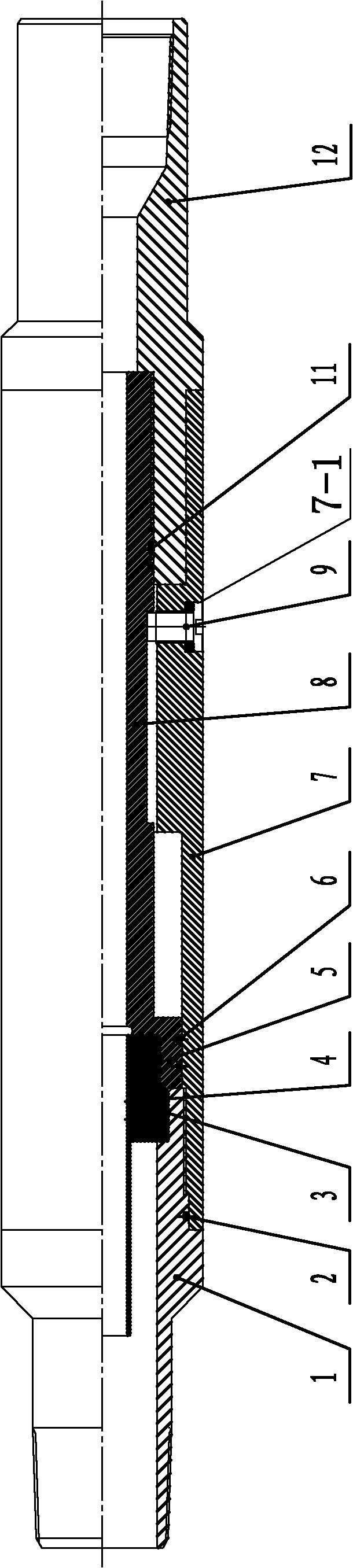
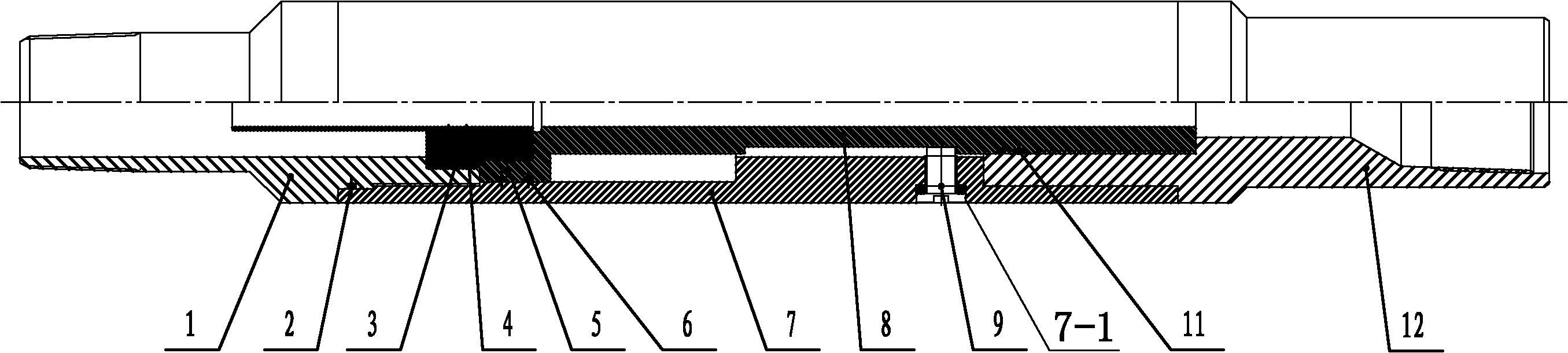
[0007] Specific implementation mode one: as figure 1 As shown, the rotating nipple used for hydraulic shaping in this embodiment includes a lower joint 1, a stop block 3, a guide block 5, a rotating sleeve 7, a steering rod 8, a positioning pin 9 and an upper joint 12. The steering rod 8 is inserted in the rotating sleeve 7, and the positioning hole 7-1 is processed on the rotating sleeve 7, and the positioning pin 9 is inserted in the positioning hole 7-1, and the positioning pin 9 is used for the steering rod 8 and the rotating sleeve 7, the lower end of the upper joint 12 is inserted into the rotating sleeve 7, and the lower end of the upper joint 12 is set on the upper end of the steering rod 8, and the upper part of the lower joint 1 is inserted in the rotating The lower end of the sleeve 7, and the upper end surface of the lower joint 1 is in contact with the lower end surface of the steering rod 8, the guide block 5 is located at the bottom of the steering rod 8, the st...

specific Embodiment approach 2

[0008] Specific implementation mode two: as figure 1 As shown, the rotating nipple in this embodiment further includes a first O-ring 2 , and the first O-ring 2 is located between the lower joint 1 and the rotating sleeve 7 . Designed in this way, it plays a sealing role. Other components and connections are the same as those in the first embodiment.

specific Embodiment approach 3

[0009] Specific implementation mode three: as figure 1 As shown, the rotary nipple in this embodiment further includes a second O-ring 4 , and the second O-ring 4 is located between the stop block 3 and the guide block 5 . Designed in this way, it plays a sealing role. Other components and connections are the same as those in the first embodiment.


PUM


Abstract

The invention discloses a rotating nipple for hydraulic shaping and relates to a rotating nipple, solving the problems that the shaping orientation of a power motor is uncertain, and the power motor has failure and is damaged under the action of hydraulic pressure and a reactive torque. In the invention, a steering rod is inserted in a rotating sleeve, and a positioning hole is arranged on the rotating sleeve; a positioning pin is inserted in the positioning hole and used for positioning the steering rod and the rotating sleeve; the lower end of an upper joint is inserted in the rotating sleeve as well as sleeved at the upper end of the steering rod; the upper part of a lower joint is inserted at the lower end of the rotating sleeve, and the upper end surface of the lower joint is in contact with the lower end surface of the steering rod; a guide block is arranged on the lower part of the steering rod, and a stop block is arranged below the guide block; and the upper end of the stop block is in contact with the guide block. The rotating nipple replaces the traditional hydraulic motor, achieves the purpose of omnibearing shaping and guarantees the shaping effect.

Description

technical field [0001] The invention relates to a rotary short joint, in particular to a rotary short joint used for hydraulic shaping of coiled tubing. Background technique [0002] At present, when using coiled tubing for hydraulic shaping, it is necessary to continuously rotate the tubing string at low speed to ensure the shaping effect, but the coiled tubing hydraulic shaping string cannot rotate. At present, a power motor is connected to the coiled tubing hydraulic shaping string to enable The lower part of the oil pipe rotates without shaping, but the speed of the oil pipe is too fast, and the shaping direction is uncertain when the shaping is continued; and the power motor is subjected to hydraulic pressure and counter torque during shaping, resulting in failure and damage to the power motor. Contents of the invention [0003] The purpose of the present invention is to solve the problem of uncertain azimuth of shaping by using a power motor and the failure and damag...

Claims


Application Information

Patent Timeline
Patent Type & Authority Applications(China)
IPC IPC(8): E21B29/00
Inventor 赵公利艾教银张国良赵恩远吕丰史健搏李艳秋
Owner DAQING OILFIELD CO LTD
Why Eureka
Try Eureka