
Method for diagnosing interturn short circuit of rotor winding

A rotor winding and turn-to-turn short-circuit technology, which is applied in the field of motor rotor winding fault diagnosis, can solve problems such as increased power loss, high sensitivity, and low sensitivity

Inactive Publication Date: 2011-03-23
EAST CHINA ELECTRIC POWER TEST & RES INST +1
View PDF4 Cites 26 Cited by
  • Summary
  • Abstract
  • Description
  • Claims
  • Application Information

AI Technical Summary

Problems solved by technology

However, this method has similar disadvantages to the resistance method, such as low sensitivity
[0007] 3. AC impedance and power loss method: the use of inter-turn short circuit has obvious demagnetization effect, resulting in a significant decrease in the total winding impedance and a significant increase in power loss
This method has high sensitivity, but it needs to be detected in the running state, especially for hydrogen cooling units, which is not easy to detect

Method used


Image

  • Method for diagnosing interturn short circuit of rotor winding
  • Method for diagnosing interturn short circuit of rotor winding
  • Method for diagnosing interturn short circuit of rotor winding

Examples


Embodiment 1

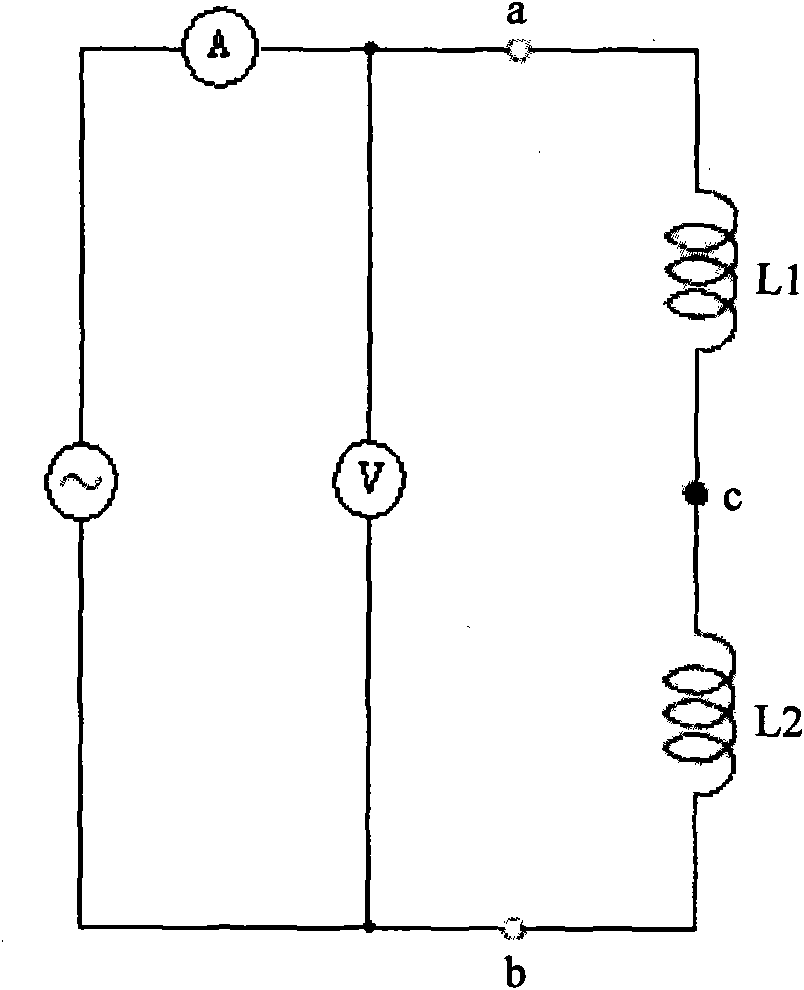
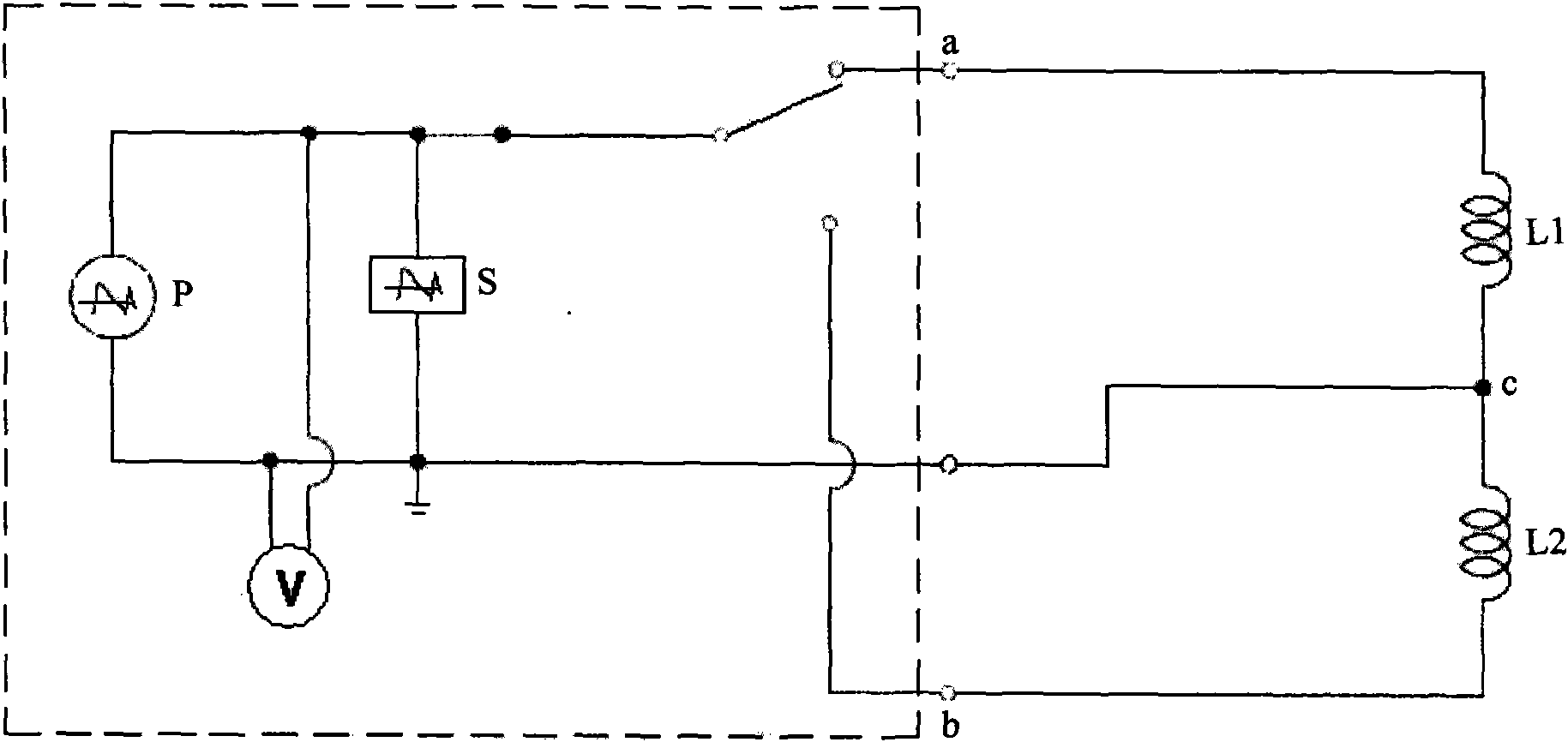
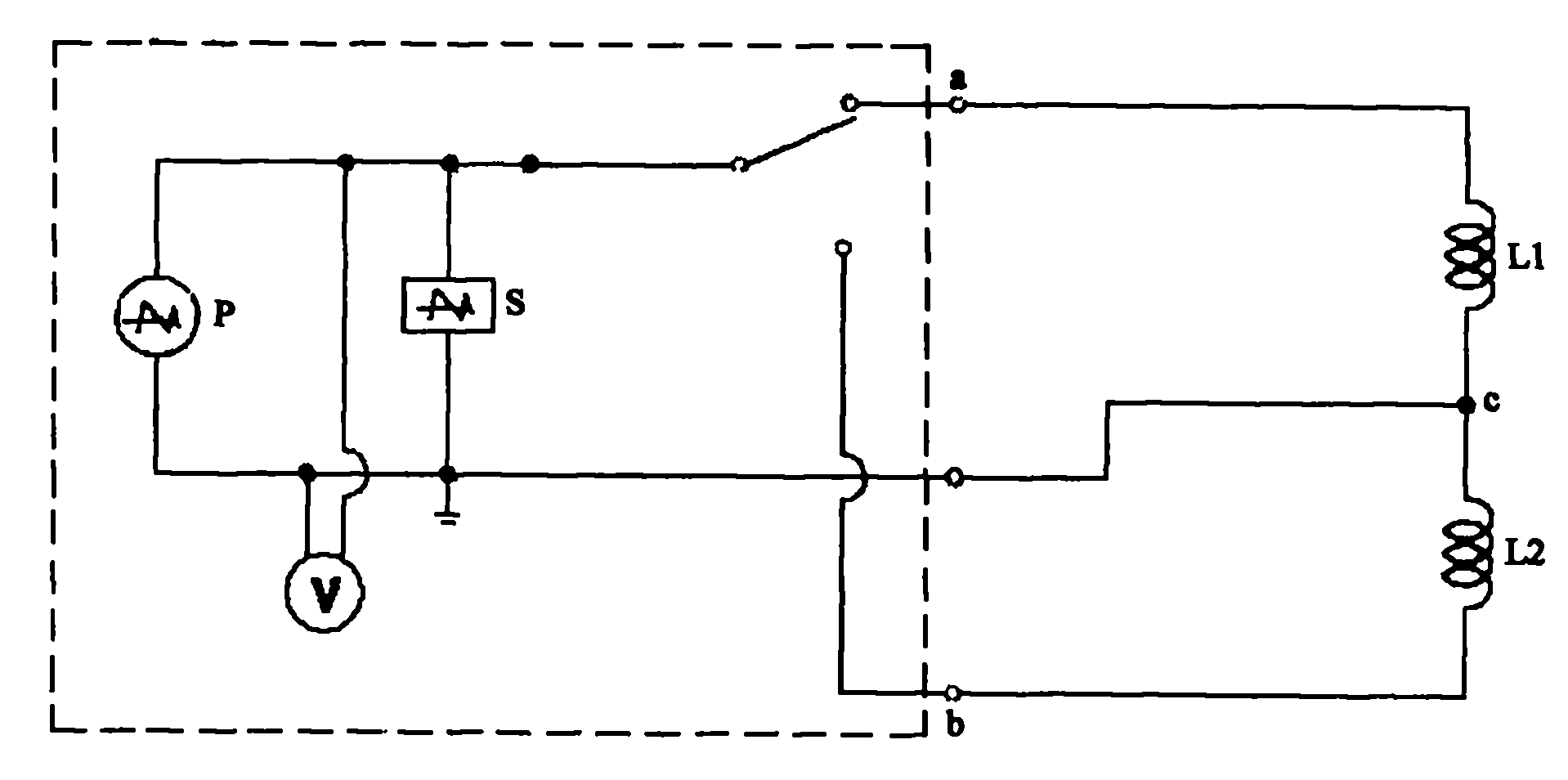
[0018] Embodiment one, such as figure 1 As shown, the AC impedance method in this method mainly applies a current excitation source between the positive lead end a and the negative lead end b of the generator rotor winding. The current requirement is greater than 1A, and the rotor winding (rotor positive coil L1 and rotor negative coil L2) the voltage at both ends, calculate the voltage and divide it by the current value to obtain the impedance value of the rotor winding, compare the calculated value with the previous value (or original value), if the relative error is less than 4%, it is considered that there is no stable turn short circuit fault. If the relative error is greater than 4%, it is considered that there is a stable turn-to-turn short circuit fault between the turns of the rotor, which needs to be dealt with. like figure 2 As shown, use the voltage oscillation generator P to apply a higher voltage oscillation wave to the positive and negative windings L1, L2 or...

Embodiment 2

[0019] Embodiment 2, for the rotor winding of the non-polar connection line, a higher voltage oscillating wave can be applied to the entire winding, and the amplitude of the oscillating wave voltage is 2 to 4 times the rated voltage of the rotor winding (depending on the rotor overvoltage level). The frequency of the oscillation wave is between 200 and 50,000 Hz. The positive electrode can be pressurized first, and then the negative electrode can be pressurized in reverse, for 3 to 5 consecutive times. The response waveforms are compared and analyzed. If the two waveforms are basically the same, or are consistent with the last waveform or the factory waveform, it is considered that there is no short-circuit fault, and the inter-turn insulation of the rotor winding is good. If there is a difference of more than 10% from the previous waveform peak value and phase, it is considered that there is a short circuit between the turns of the rotor winding.

[0020] The current public t...


PUM


Abstract

The invention discloses a method for diagnosing an interturn short circuit of a rotor winding. The method comprises the following steps of: giving a judgment that a rotor winding has interturn stability short circuit fault through a rotor alternating current impedance test; then judging whether the rotor winding has the interturn instability or stability short circuit fault or not by combining a voltage oscillation wave test; and blending the results of the alternating current impedance test and the oscillation wave test to analyze and find out the position of a short circuit point so as to process the fault in time and recover the rotor winding to be insulated. The invention has the characteristics of simple and convenient measurement, low cost and good practical effect and can be used for detecting and diagnosing the interturn faults of rotors of steam turbine generators, water wheel generators and electric motor generator in a static state.

Description

technical field [0001] The invention relates to a method for diagnosing faults of motor rotor windings, in particular to a method for diagnosing short circuits between turns of rotor windings. Background technique [0002] The rotors of large synchronous motors (including steam turbine generators, water turbines and motor generators) generally adopt a wound structure, and the inter-turn insulation thickness is only 0.3-0.5mm. Inter-turn short circuit is a relatively easy fault. Turn-to-turn short circuit will occur in the rotor winding due to the following reasons: a. Manufacturing reasons: Due to poor manufacturing process, the inter-turn insulation is damaged during the process of winding off-line and shaping; or the corner burrs of the winding copper conductor are not polished, and the conductive metal Chips, etc. are not cleaned thoroughly, which can easily cause inter-turn short circuit. b. Reasons for operation: The long-running generator, under the action of electric...

Claims


Application Information

Patent Timeline
IPC IPC(8): G01R31/06G01R31/34
Inventor 李福兴苏磊
Owner EAST CHINA ELECTRIC POWER TEST & RES INST
Learn More